
Data Sheet

iolinker Family Data Sheet
9 Pin Configurations
9.1 Signal Descriptions
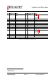
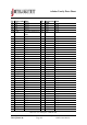
9.1.1 General Pin Listing
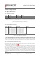
Name Pin type Function Note
EN Input Chip enable
∗
Pull low to activate chip
INT Open collector output Interrupt pin
∗∗
Use external pull-up
∗
When the chip is not enabled, all outputs are in their default state, pin links are inactive and no communi-
cation is processed.
∗∗
Informs about updates of input GPIOs, multiple devices can be connected on a single interrupt bus line.
Table 17: Enable and interrupt pin description
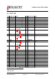
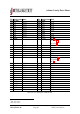
9.1.2 Slave Address Pin Listing
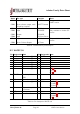
Name Pin type Function Note
IN1 Input, internal pull-up Slave address 1st bit, LSB –
IN2 Input, internal pull-up Slave address 2nd bit –
IN3 Input, internal pull-up Slave address 3rd bit –
IN4 Input, internal pull-up Slave address 4th bit –
IN5 Input, internal pull-up Slave address 5th bit –
IN6 Input, internal pull-up Slave address 6th bit –
IN7 Input, internal pull-up Slave address 7th bit, MSB –
Table 18: Slave address pin description
The 7 bit slave address of the device can be assigned using the hardware address pins IN1
(LSB) to IN7 (MSB), which are connected to an internal pull-up resistor by default. The user
can encode the slave address by puling the appropriate pins low. A high pin state is regarded
as 1 bit, a low pin state as 0. Thus, if all pins are left unconnected, the slave address is 0x7f.
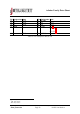
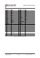
9.1.3 Communication Interface Pin Listing
Depending on chip version, the same hardware pins are used for one of the three communi-
cation interfaces, as described in table 19.
Note that the UART version requires an external pull-up (around 10kOhm) on its transmit
pin, for it is designed to run on a shared open collector bus line. For the UART master,
this approach is entirely transparent: Only the addressed iolinker chip will reply to any given
message and pull low the UART transmit line. To avoid harming any of the connected chips
in case of incorrectly assigned slave addresses, that would lead to a bus conflict during replies,
an additional 10kOhm resistor can be used to connect each individual device to the shared
bus line.
c
2017 jInvent. The specifications and information herein are subject to change without notice.
www.jinvent.de Page 21 iolinker introduction