
User's Manual
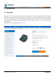
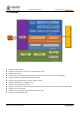
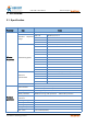
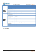
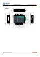
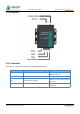
Table Of Contents
- USR-G786-G User Manual
- 1.Introduction
- 2.Get Started
- 3.Utility Configuration
- 4.Serial Port
- 5.Selecting an Operating Mode
- 6.General Function
- 7.AT Command Set
- 7.1.AT Command Examples
- 7.2.AT Command Set
- 7.2.1.AT
- 7.2.2.AT+H
- 7.2.3.AT+Z
- 7.2.4.AT+E
- 7.2.5.AT+ENTM
- 7.2.6.AT+WKMOD
- 7.2.7.AT+CMDPW
- 7.2.8.AT+STMSG
- 7.2.9.AT+RSTIM
- 7.2.10.AT+CSQ
- 7.2.11.AT+SYSINFO
- 7.2.12.AT+UCPIN
- 7.2.13.AT+RELD
- 7.2.14.AT+CLEAR
- 7.2.15.AT+CFGTF
- 7.2.16.AT+VER
- 7.2.17.AT+SN
- 7.2.18.AT+ICCID
- 7.2.19.AT+IMEI
- 7.2.20.AT+CIP
- 7.2.21.AT+LBS
- 7.2.22.AT+CCLK
- 7.2.23.AT+PING
- 7.2.24.AT+UART
- 8.Contact Us
- 9.Disclaimer
- 10.Update History

USR-G786-G User Manual Technical Support: h.usriot.com
Jinan USR IOT Technology Limited www.usriot.com
10
2.2.2.Interface
2.2.3.Indicators
There are four indicators on USR-G786-G, PWR,WORK,NET,LINKA.
Indicator
Function
Status
POWER
Power indicator
Always on when power supply
working normally
WORK
System operation indicator.
Flashing after system running
NET
Network status indicator
Always on after registering the
network
LINKA
Socket A indicator
Always on after socket A is
connected