
User's Manual
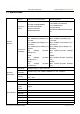
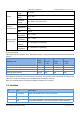
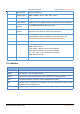
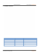
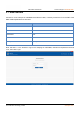
Table Of Contents
- USR-G809 User Manual
- 1.Introduction
- 1.1.Overview
- 1.2.Features
- 1.3.Specification
- 1.4.Interface
- 1.5.Indicator
- 1.6.Dimensions
- 2.General Function
- 2.1.Web Interface
- 2.2.Hostname
- 2.3.User Password Settings
- 2.4.Reboot Timer
- 2.6.Reboot
- 2.7.Reload Button
- 3.Interface
- 3.1.WAN Interface
- 3.2.LAN Interface
- 3.3.Cellular Network Interface
- 3.4.WLAN Interface
- 3.5.VLAN
- 3.6.DIDO
- 4.Network
- 4.1.Network Switch
- 4.2.DHCP
- 4.3.Hostnames
- 4.4.Static Routes
- 4.5.Diagnostics
- 5.VPN
- 5.1.PPTP Client
- 5.2.L2TP Client
- 5.3.IPSec
- 5.4.OpenVPN
- 5.5.GRE
- 6.Firewall
- 6.1.General Settings
- 6.2.NAT
- 6.3.Traffic Rules
- 6.4.Access Restriction
- 7.Serial Port
- 7.1.Connecting Hardware
- 7.2.Serial Port Settings
- 7.3.Operation Mode
- 7.4.General Function
- Protocol description:
- 8.USR Cloud
- 8.1.Cloud Monitor
- 8.2.Add device
- 8.3.Network Status
- 8.4.Parameter Configuration
- 8.5.Firmware Upgrade
- 8.6.Records of device
- 8.7.Alarm
- 8.8.Remote Configuration
- 9.Services
- 9.1.Syslog
- 9.2.NTP
- 9.3.Email
- 9.4.SMS
- 9.5.Alert
- 9.6.Alert Examples
- 9.7.Call Reboot
- 9.8.Geolocation
- 9.9.DDNS
- 10.AT Commands Settings

USR-G809 User Manual Technical Support:
h.usriot.com
Jinan USR IOT Technology Limited www.pusr.com
7
4
USB interface
Firmware upgrading
5
Indicator lights
PWR、WORK、WLAN、USR、NET、SIG*3
6
SIM slot
3V/1.8V SIM card, ESD 15KV
7
Reload button
Restore to factory settings/restore the firmware/upgrade via USB port
8
WIFI antenna
interface
2* standard SMA male antenna connector
9
4G antenna
interface
2* standard SMA female antenna connector
4G-M is the main antenna, 4G-D is the auxiliary one.
10
Ground screw
Router grounding helps prevent the noise effect due to
electromagnetic interference (EMI). Connect the router to the
site ground wire by the ground screw before powering on.
11
TF card slot
Reserved interface.
12
Terminal interface
V+,V- : power interface, built-in anti-reverse protection
GNG: Ground terminal
Tx/B: RS232 or RS485, can be set via webpage
Rx/A: RS232 or RS485, can be set via webpage
DI1、DI2、DO1、DO2:DIDO terminal interface
COM: DO loop terminal.
13
TBD
Debug interface.
1.5. Indicator
Item
Description
PWR
Power indicator, always on red after powered on.
WORK
Work indicator, 1 sec blink after booting.
WLAN
WiFi indicator, always on green when Wi-Fi is enabled and working properly.
USR
User-defined indicator, can be set via the webpage(socket, VPN...)
NET
Always on after connecting to the network. Two colors indicate 4G network, green
indicates 3G and red indicates 2G.
SIG(1-3)
Signal strength indicator, the more lights on, the stronger the signal.