
User's Manual

CONTENTS
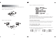
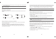
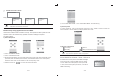
Step 2: Insert the SIM
1: Easy Install
Step 1: Open the housing
-02-
Figure -1-
Figure -2-
After unpacking the kit and making sure that you have all the necessary equipments, it is
recommended that you install the system as following:
-03-
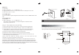
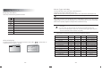
Step 3: Connect external devices
Wired Siren Connection
Note: The wired siren is invalid with backup battery.
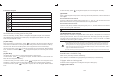
AUX Power Output Terminal
Alarm Linkage Output: PGM
only
Figure -3-
Figure -4-1-
Low voltage device / control module
External Power
(İDC25V)
Alarminput
Figure -4-2-
The max drive of BELL terminal is 400mA / 12VDC. Connect the bell power line to “BELL” and
“GND”. Users can try to program via keypad to set if the siren beeps and how long it beeps.
AUX supplies power output for wired detectors (AC Operated: 10-12V, Battery Operated: 6-8V,
max current: 100mA. It may cause abnormal working for wired detector under low battery).
The maxload of PGM output is DC25V/500mA. Boolean value is output with PGM on
connected with GND of PCB board.
PGM can connect to wired siren, indicator, electronic lock(Figure 4-1), and it also connect
CCTV camera and DVR for alarm input(Figure 4-2).