
User's Manual

T
ally Dascom 2610
99
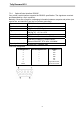
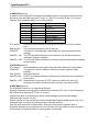
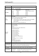
Interface cable (serial interface)
The cables used must be shielded. The cable shield must be connected to the connector
shield on both ends.
PC/AT(9 Pin) Printer(9 Pin)
RxD 2 3 TxD
TxD 3 2 RxD
CTS 8 4 DTR/RDY
SG 5 5 SG
DSR 6
DTR 4
PC/AT(25 Pin) Printer(9 Pin)
FG 1 FG
TxD 2 2 RxD
RxD 3 3 TxD
CTS
5
4DTR/RDY
SG 7 5 SG
DSR 6
DTR 20
It depends on the menu setting whether DTR or RDY (Ready) is active at Pin 4.
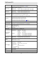
◆
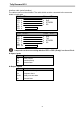
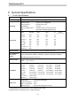
Input signals
Signal Function
CTS
DSR
RxD
Clear to Send
Data Set Ready
Receive Data
◆
Output signals
Signal Function
DTR
RTS
READY
TxD
Data Terminal Ready
Request to Send
Ready to receive data
Tra nsmit Da t a
PC/AT(25 Pin) Printer(9 Pin)
PC/AT(9 Pin) Printer(9 Pin)