
Product Manual


7
6.0 Setup and assembly
Read and understand all
assembly instructions before attempting
assembly. Failure to comply may cause serious
injury.
6.1 Unpacking and cleanup
Inspect contents of shipping container for shipping
damage. Report any damage to your distributor.
Remove all contents from carton, and compare to
the contents list in this manual. Report any part
shortages to your distributor.
Do not discard carton or packing material until
machine is assembled and working properly.
Exposed metal areas may have a rust protectant
applied. Remove this with a soft rag and solvent
such as kerosene. (Do not use gasoline, paint
thinner, acetone, etc., as these will damage painted
surfaces.)
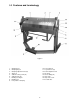
6.2 Contents of shipping container
1 Box and Pan Brake
2 Support legs with screws
1 Instructions and Parts Manual (not shown)
1 Warranty Card (not shown)
6.3 Tools required for assembly
8mm hex key
6.4 Assembly
Numbers in parentheses refer to items in Figure 2.
1. Remove any straps or screws securing the
brake, and raise machine using properly rated
lifting equipment. See Figure 3 for lifting strap
placement.
Figure 3
Continue to stabilize machine
while installing support legs.
2. Attach the two leg extensions (11) with the
provided socket head screws and flat washers.
3. Secure brake to floor using lag screws or similar
system. See diagram, Figure 1. Also level the
brake; use shims if needed.
4. The stop collar screw (16) has been tightened
for shipping purposes. This screw must be
loosened to allow clamping machine
adjustments.
7.0 Operation
Numbers in parentheses refer to items in Figure 2.
7.1 Finger spacing
Upper (2) and lower (7) fingers are mounted on T-
nuts that slide within the underlying channel.
Remove fingers by removing the screw(s); or
reposition fingers at any place along the beam by
loosening screw and sliding the T-nuts. Firmly
tighten screws on fingers before operating.
7.2 Adjusting setback
The bending leaf lower fingers (7) must be adjusted
for proper clearance or “setback” (A, Figure 3)
based on material thickness (B, Figure 3).
Generally, setback for material within four gauges of
capacity should be twice the thickness of material.
For lighter gauges, use 1-1/2 times the material
thickness. Consult a machinery handbook for bend
allowances.
Figure 3
1. Loosen setback locking screws (5).
2. Rotate setback knobs (6) in equal amounts
(clockwise decreases distance). Refer to
adjoining scale, marked with 0.002-inch
graduations.
Note: When increasing distance (counter-
clockwise), you may have to pull back slightly
on the bending leaf to take up any backlash.
3. Bring clamping leaf into position and check
setback.
4. Repeat above steps until proper distance is
achieved.