This .pdf document is bookmarked Operating Instructions and Parts Manual Dual-Sided 16ga. Box and Pan Brake Model PBF-1650D JET 427 New Sanford Road LaVergne, Tennessee 37086 Ph.: 800-274-6848 www.jettools.com Part No.
11. Do not operate this machine while tired or under the influence of drugs, alcohol or any medication. 12. Remove adjusting keys and wrenches. Form a habit of checking to see that keys and adjusting wrenches are removed from the machine before turning it on. 1.0 IMPORTANT SAFETY INSTRUCTIONS 13. Keep safety guards in place at all times when the machine is in use. If removed for maintenance purposes, use extreme caution and replace the guards immediately after completion of maintenance.
26. Sheet metal stock has sharp edges; use caution when handling to prevent cuts. 28. Do not exceed rated capacity of brake. 29. The brake should be secured to floor with appropriate fasteners. 27. Keep hands clear of bending area while operating. Familiarize yourself with the following safety notices used in this manual: This means that if precautions are not heeded, it may result in minor injury and/or possible machine damage.
3.0 Table of contents Section Page 1.0 IMPORTANT SAFETY INSTRUCTIONS ....................................................................................................... 2 2.0 About this manual .......................................................................................................................................... 3 3.0 Table of contents ............................................................................................................................................ 4 4.
4.0 Specifications for 16x50 Box and Pan Brake Model Number ...................................................................................................................................... PBF-1650D Stock Number ............................................................................................................................................. 752130 Materials: Frame ..........................................................................................................................
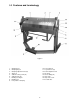
5.0 Features and terminology Figure 2 1. 2. 3. 4. 5. 6. 7. 8. 9. Clamping leaf Clamping fingers Clamping adjustment nut (x2) Stop bolt Setback locking screw (x2) Setback knob (x2) Bending leaf fingers Bending leaf Foot pedal for clamping 10. 11. 12. 13. 14. 15. 16. 17.
6.0 Setup and assembly Read and understand all assembly instructions before attempting assembly. Failure to comply may cause serious injury. 2. Attach the two leg extensions (11) with the provided socket head screws and flat washers. 3. Secure brake to floor using lag screws or similar system. See diagram, Figure 1. Also level the brake; use shims if needed. 4. The stop collar screw (16) has been tightened for shipping purposes. This screw must be loosened to allow clamping machine adjustments. 6.
5. Tighten locking screws (5). If a crown develops in the material, this can be adjusted out by loosening or tightening the hex nuts on the crown adjustment rod (12). Note: This rod has been correctly set by the manufacturer and should only be adjusted when needed. 4. Align material in machine and press foot pedal until it locks. 5. Raise bending leaf to desired angle. 6. Lower bending leaf and press foot pedal lock to release material. 7.3 Adjusting clamping pressure 8.
10.1.
.1.2 PBF-1650D Box and Pan Brake – Parts List Index No Part No Description Size Qty 1 ................ H40-210 .................... Adjusting Nut ........................................................... ...................................... 2 2 ................ PBF1650D-02 ........... Clamping Leaf. ........................................................ ...................................... 1 3 ................ PBF1650D-03 ........... T-Nut ......................................................
Index No Part No Description Size Qty 39 .............. PBF1650D-39 ........... Setback Knob .......................................................... ...................................... 2 40 .............. PBF1650D-40 ........... Operating Handle .................................................... ...................................... 2 41 .............. PBF1650D-41 ........... Adjusting Rod .......................................................... ...................................... 1 42 ...
11.0 Warranty and service JET warrants every product it sells against manufacturers’ defects. If one of our tools needs service or repair, please contact Technical Service by calling 1-800-274-6846, 8AM to 5PM CST, Monday through Friday. Warranty Period The general warranty lasts for the time period specified in the literature included with your product or on the official JET branded website. • JET products carry a limited warranty which varies in duration based upon the product.
This page intentionally left blank.
This page intentionally left blank.
This page intentionally left blank.
427 New Sanford Road LaVergne, Tennessee 37086 Phone: 800-274-6848 www.jettools.