
Use and Care

Connecting your new 737
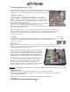
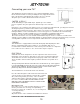
This dishwasher must be installed on a level, rigid, nonflammable surface.
Ensure that the machine is level by installing the feet (shipped in the wash
tank of the machine) and adjusting the leveling. Be sure to provide
adequate space for water, drain and electrical connections.
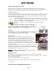
**WATER SUPPLY**
A 3/4” NPT fitting is required with 30 psi. dynamic pressure. A water
pressure regulator* may be required. The water flow pressure cannot be
less
than 30 psi or exceed 30 psi. If the water pressure exceeds the prescribed amount, you will get inconsistent
washing temperature, premature failure and thus may void the warranty.
Incoming water temperature must be 140º F (60º C). An easily accessible shut-off valve is recommended,
making installation, service and maintenance easier. This type hose is standard for most warewashing
machines. Fittings should be available from your local hardware or plumbing supply house.
Flexible hoses must be used to make installation, servicing and maintenance easier.
Ensure that the water is free from calcium and hard water deposits. For these situations, an inline water
cartridge system is highly recommended. Build-up of calcium and lime deposits in the washer may occur and
servicing will be required on a more frequent basis which will not be covered by the warranty.
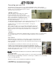
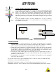
**DRAIN**
This dishwasher is equipped with an automatic drain pump that will pump the drain
water to a maximum height of 36" (0.9 meter). A 1" ID flexible drain hose is
recommended to facilitate maintenance and servicing of the machine. It is important
not to reduce the size of this hose. A 1" check-valve* may be required.
ELECTRICAL
A 208-240 volt, 60 Hz, Single Phase circuit is required for this unit. Check the
rating plate on the machine for amp draw. In spite of the fact that the rating plate
shows 208 volts, the unit is designed function properly on 208 volts to 240 volts.
There should be sufficient cable length to permit the machine to be pulled out for
service.
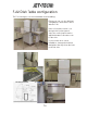
The top & back panels must be removed for the electrical hook -up. The top panel
is secured by Phillips head screws. Once the screws removed, the panel should be
slid to the back and lifted. The back panel is held by 6 screws. Remove them,
pull the top away from the machine and lift the panel.
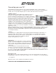
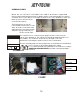
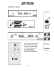
The terminal block is located at the back of the machine.
Pass the cable through the cable strain relief at the back and
connect the wires to the terminals L1 (brown wire), L2 (blue
wire) & Ground (yellow & green wire). There should be
sufficient cable length to permit the machine to be pulled out
for service. DO NOT TURN ON THE POWER TO THE
MACHINE UNTIL THE WATER SUPPLY & DRAIN LINES
HAVE BEEN CONNECTED.
G
L1
W
ater
IMPORTANT NOTE
Reasonable access to and around the machine for service
must be provided. Disconnecting of hard plumbing or
removal of counter tops or cabinets, etc., for servicing is not
covered by warranty.
* - not supplied
All panels must be on the unit when the installation is finished.
** SEE PAGE 6 FOR FURTHER IMPORTANT DETAILS**
15
L2
W
ater
In
Out