JW10A 10" Powered Subwoofer in a Vented Enclosure with Multiple Mounting Options INSTALLATION/OWNER'S MANUAL
PREPARATION Getting Started Thank you for purchasing the Jensen JW10A 10" vented enclosure with built-in amplifier. Although Jensen has attempted to ensure the information in this manual is accurate, please be aware that any part of it is subject to change without notice. Please read entire manual before installation. Due to the technical nature of amplifiers, it is highly recommended that your Jensen JW10A is installed by a professional installer or an authorized dealer.
INSTALLATION Safety First ! CAUTION The following instructions are designed to ensure safety during installation and use of the JW10A. Failure to heed these instructions can result in injury or damage to the unit or vehicle. The following installation instructions are intended to be used as a basic guideline. If you feel unsure about installing this speaker system yourself, Jensen recommends acquiring the services of a professional car audio installation center.
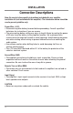
INSTALLATION Connection Descriptions Note: Be sure to follow specific instructions included with your amplifier installation kit (not included with this amplifier). The information below should be used a general guideline only. Power Wire (+12V) • Disconnect negative battery terminal before proceeding. Consult a qualified technician for instructions if you are unsure. • Plan wire routing before cutting any wires to length. Begin by routing the power +12V wire from the battery to the amplifier location.
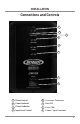
INSTALLATION Connections and Controls 1 2 3 4 5 6 7 8 1 Phase Control 5 Crossover Frequency 2 Power Indicator 6 Bass EQ 3 Protect Indicator 7 Fuse (15A) 4 Input Level Control 8 Power / Input Connector 5
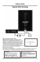
INSTALLATION Typical Wire Routing High Level Input (Speaker Wire) High level inputs should only be used when RCA outputs are not available from the head unit. Connect the head unit speaker outputs to the high level input connector as shown below. The black wire (signal reference ground) may or may not require a connection to chassis ground - depending on your particular installation. Do not use both low and high level inputs at the same time. Connect only one or the other.
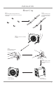
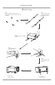
INSTALLATION Mounting Step 1 Secure the supplied mounting brackets to the desired location of your vehicle’s trunk or hatchback as illustrated. Step 2 Lace the mounting straps so that they pass through the brackets mounted on the base. Step 3 Place the JW10A on the brackets as shown. Step 4 Lace the mounting straps through the buckles. Step 5 Pull the straps to fasten the buckles as tightly as possible.
INSTALLATION Mounting Step 1 Secure the supplied mounting brackets to the desired location of your vehicle’s trunk or hatchback as illustrated. Step 2 Lace the mounting straps so that they pass through the brackets mounted on the base. Step 3 Place the JW10A on the brackets as shown. Step 4 Lace the mounting straps through the buckles. Step 5 Pull the straps to fasten the buckles as tightly as possible.
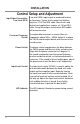
INSTALLATION Control Setup and Adjustment Input Signal Connections Low Level (RCA) Crossover Frequency Control Phase Control Low level (RCA) input signal is preferred for best performance. Typical trunk-mount installations require a 17-20 foot RCA cable. Most trucks and behind-seat applications require a 6-12 foot RCA cable. Using twisted pair construction RCA cables will minimize noise. The adjustable crossover is used to filter out frequencies above 50Hz ~ 250Hz.
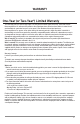
WARRANTY One-Year (or Two-Year*) Limited Warranty This warranty gives you specific legal rights. You may also have other rights which vary from state to state. Namsung America Inc warrants this product to the original purchaser to be free from defects in material and workmanship for a period of one year (or two years*) from the date of the original purchase.
INSTALLATION Notes For Your Records Please keep your original sales receipt and be prepared to provide this receipt in the event you require service, as your original receipt is considered the best proof of purchase and indicates the date you purchased your Jensen product. Dealer Name Dealer Phone Purchase Date Register Your Product Register your product online at www.jensenmobile.
INSTALLATION Specifications Maximum Output Power 300 watts Continuous Output Power 100 watts Frequency Response 40-250Hz Operating Voltage Impedance 11.0VDC ~ 14.4VDC Allowed 4 Ohms Crossover Frequency 50–250Hz Amplifier Type Class A/B Phase Fuse Dimensions 0–180 degrees 15 amp ATO Depth (standing): 7.87” / Depth (laying down): 12.6” Height (standing): 12.6” / Height (laying down): 7.87” Width (standing): 16.54” / Width (laying down): 16.
Customer Support 1-888-921-4088 (Monday-Friday, 9AM-5PM EST) https://www.jensenmobile.com Designed and Engineered in USA All rights reserved. No part of this publication may be reproduced, distributed, or transmitted in any form or by any means, including photocopying, recording, or other electronic or mechanical methods, without the prior written permission of NAMSUNG AMERICA INC. Namsung America Inc. ©2022 Namsung America Inc. All rights reserved.