
Dimensions Guide

JENN-AIR DETAILED PLANNING DIMENSIONS
IMPORTANT: Dimensional specifications are provided for planning purposes only.
Do not make any cutouts based on this information. Refer to the Installation Guide before
selecting cabinetry, verifying electrical/gas connections, making cutouts or beginning installation.
All Jenn-Air® appliances are appropriately UL, CUL or CSA approved. W11192706A
10/17
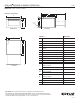
UNDER COUNTER MICROWAVE OVEN WITH DRAWER DESIGN
JMDFS24GS – 23
7
/8” x 15
13
/32” x 24
9
/16”
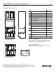
OPENING/CLEARANCE DIMENSIONS
MODEL # JMDFS24GS
in cm
A Width of cutout (min.-max.) 24
3
/16 -
24
1
/2
61.4-
62.2
B Width between side cleats 22
1
/8 56.2
C Height of cutout 17 43.2
D Height from top of cutout to
platform
16
1
/8 41.0
E Width of suggested electrical
receptacle location
4
1
/2 11.4
F Height of suggested electrical
receptacle location
3 7.6
G
Top of cutout to bottom of oven
(min.)
2 5.1
Top of cutout to bottom of
countertop
(min.)
2 5.1
H Bottom of cutout to top of cabinet
door (min.)
2 5.1
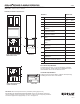
I
Depth of cutout (min.) with flush
receptacle
23
1
/2 59.7
with non-flush receptacle 28 71.1
J Depth of side cleat
0.39
K Depth from face of cabinet to front
of platform
1
7
/8 4.8
L Depth from back of installed
microwave to back of cabinet
3
1
/2 8.9
e
Recommended electrical connection location
ELECTRICAL REQUIREMENTS
120 volt, 60 Hz, AC only, 15- or 20-amp fused, grounded
circuit is required. A time-delay fuse or dedicated circuit is
recommended. Do not use an extension cord.
LOCA
TION REQUIREMENTS
Support structure must be able to support 100 lb (45.4 kg)
including microwave oven and contents.
A
B
C
D
e
I
F
K
J
DE
G
H
Side
Cleat*
Bottom Platform
Bottom Platform
I
L
K
J
FRONT VIEW-INSTALLATION
UNDER SINGLE OVEN
A
B
e
D
F
E
G
H
Bottom PlatformBottom Platform
C
D
Side
Cleat*
FRONT VIEW-INSTALLATION
UNDER COUNTERTOP
Power Supply
Location
BACK VIEW
SIDE VIEW
3 of 3
JENN-AIR DETAILED PLANNING DIMENSIONS
®
1
17
/32