JEFF ROWLAND D E S I G N G R O U P
Model 2 Stereo Power Amplifier Owner’s Manual
Introduction Welcome to the Jeff Rowland Design Group “family” and congratulations on your purchase of what is unquestionably one of the world’s finest audio power amplifiers. þ With its combination of industrial grade active and passive devices, þ Jeff Rowland Design Group, Inc. 2911 North Prospect Street precision electronic circuitry and accurately machined chassis components throughout, your Model 2 Amplifier will offer Colorado Springs, CO 80907 you many years of musically satisfying enjoyment.
Product Features þ XLR Balanced Input jacks for balanced (Differential Mode™) system configurations þ Quiet, transient-free operation during power and function mode switching þ XLR to RCA Input adapters included þ Automatic input muting under anomalous input or output operating conditions þ User-selectable overall gain of 26 or 32 dB þ þ User-selectable input impedance of 36kΩ (HI) or 600Ω (LO) Balanced Differential Mode™ circuit topology implemented from input to output þ All internal signal
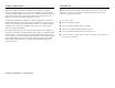
Contents 1 6 4 2 3 5
Initial Inspection Contents Inspect the shipping container for damage. If the shipping container, packing material, amplifier or accessories are damaged or missing, notify your dealer and the shipper (if a claim is to be made). Note: Many shippers require notification and an inspection within twenty-four (24) hours of delivery to ascertain the nature of damages incurred.
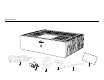
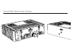
Front & Rear Panel Function Controls 2 A 1
Front & Rear Panel Function Controls Before attempting any system interconnection, please familiarize yourself with the front and rear panel controls of the Model 2 Amplifier. The descriptions below refer to the numbers associated with the features in the diagram above. Front Panel A FRONT PANEL STANDBY/POWER button: Press to operate Amplifier in standby mode. This button will illuminate when the Amplifier is operational.
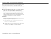
Rear Panel Power Connections 2 1 3
Installation Rear Panel Power Connections Locate the Amplifier as close as possible to its final installation point. Allow access to the rear panel for making connections. Important: Please strictly follow the steps in order as outlined below The Model 2 Amplifier is convection cooled, eliminating the need for fan or forced air cooling. When operating, the chassis should have at least two (2) inches of air space around the heatsink areas.
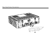
Signal Connections 1 4 3 2 3
Signal Connections The Model 2 amplifier offers unprecedented compatibility with associated audio components. When connecting or disconnecting speaker or interconnect cables, it is only necessary that the FRONT PANEL STANDBY/ POWER button be pressed to switch the amplifier to standby mode. The button will not be illuminated in this mode. 1 When installing the interconnect cables, a slight click may be heard when the XLR interconnect plugs are installed correctly and latched.
Operation After following the procedures outlined in the Installation/Rear Panel Power Connections and Signal Connections sections, the Amplifier can be turned on by pressing the FRONT PANEL STANDBY/POWER button. Allow approximately twenty (20) minutes for the amplifier to reach operating temperature and maximum performance potential.
Performance Specifications Power Consumption 25 watts standby; 175 watts operating, idle; 400 watts maximum 75 watts 150 watts Inputs Power Bandwidth 0.1 Hz to 160 kHz, -3 dB Unbalanced Balanced User selectable on rear panel With supplied XLR/RCA adapter 2 XLR connectors Slew Rate 80 volts per microsecond Outputs 1 pair binding posts per channel THD and Noise Less than 0.05% at rated power Dimensions 17.5 in. W x 14.25 in. D x 5.25 in. H 44.5 cm W x 36.2 cm D x 13.
Basic Troubleshooting A summary of fault conditions, their causes and remedies, are listed below. The Model 2 Amplifier can produce high power levels which, without well designed protection circuitry, could damage loudspeakers. Therefore, most fault conditions which may occur during use will be indicated by the Model 2 reverting to a standby condition. JRDG = Jeff Rowland Design Group, Inc.
Condition Cause Remedy FRONT PANEL STANDBY/POWER button illuminates normally but RIGHT, LEFT or both Amplifier CHANNELS do no operate or warm up to normal operating temperature. Internal DC fuses defective. Consult dealer or JRDG. AC MAINS CIRCUIT BREAKER (rear panel) switches off or will not remain on. AC mains service voltage too high for Amplifier. Reconfigure Amplifier to proper AC mains voltage operation. Consult dealer or JRDG. 50/60 Hz hum noise in loudspeakers.
If you have any additional questions regarding installation or operation, please contact your authorized Jeff Rowland Design Group Dealer.