RM3 SERIES BACKREFLECTION METER USER’S MANUAL RM3 SERIES BACKREFLECTION METER User’s Manual 10112341 Rev 002 Page 1 of 39
RM3 SERIES BACKREFLECTION METER USER’S MANUAL Contents Safety Information, Instructions, and Symbols.......................................................................4 Safety Information ...........................................................................................................4 Classification .......................................................................................................4 Disconnecting from Line Power ............................................................
RM3 SERIES BACKREFLECTION METER USER’S MANUAL Front Panel....................................................................................................................22 Rear Panel ....................................................................................................................23 Termination Techniques................................................................................................23 Termination Techniques for Single-mode Fiber (except 980 nm) ......................
RM3 SERIES BACKREFLECTION METER USER’S MANUAL Website: http://www.jdsuniphase.com Safety Information, Instructions, and Symbols Safety Information Classification The RM Series Backreflection Meter consists of an exposed metal chassis that is connected directly to earth via a power cord and, therefore, is classified as a Class 1 instrument. Disconnecting from Line Power Some of the circuits are powered whenever the unit is connected to the AC power source (line power).
RM3 SERIES BACKREFLECTION METER USER’S MANUAL Under the laser classification of the US Food and Drug Administration (FDA) Center for Devices and Radiological Health (CDRH), the laser contained in the unit is a Class 1 laser.
RM3 SERIES BACKREFLECTION METER USER’S MANUAL Safety Instructions The following safety instructions must be observed whenever the unit is operated, serviced, or repaired. Failure to comply with any of these instructions or with any precaution or warning contained in the user’s manual is in direct violation of the standards of design, manufacture, and intended use of the unit. JDS Uniphase assumes no liability for the customer’s failure to comply with any of these safety requirements.
RM3 SERIES BACKREFLECTION METER USER’S MANUAL not use repaired fuses, and avoid any situations that can short-circuit the fuse. • Unless absolutely necessary, do not attempt to adjust or perform any maintenance or repair procedure when the unit is opened and connected to a power source. • Repairs are to be carried out only by a JDSU qualified technician. • Do not attempt any adjustment, maintenance, or repair procedure to the unit’s internal mechanism if immediate first aid is not accessible.
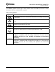
RM3 SERIES BACKREFLECTION METER USER’S MANUAL Safety Symbols The following symbols and messages can be marked on the unit (Table 2). Observe all safety instructions that are associated with a symbol. Table 2: Safety Symbols Symbol Description Laser safety. See the user’s manual for instructions on handling and operating the unit safely. See the user’s manual for instructions on handling and operating the unit safely. Electrostatic discharge (ESD).
RM3 SERIES BACKREFLECTION METER USER’S MANUAL Compliance CE Compliance The unit has been designed and tested to comply with directive 73/23/EEC and its subsequent amendments by the European Community (EC or CE). The directive relates to electrical equipment designed for use within certain voltage limits. It ensures that electrical equipment is constructed with good engineering practice in safety matters.
RM3 SERIES BACKREFLECTION METER USER’S MANUAL non-conductive pollution occurs. Occasionally, however, a temporary conductivity caused by condensation must be expected.
RM3 SERIES BACKREFLECTION METER USER’S MANUAL General Information and Specifications General Information This user’s manual for the RM3 Series Backreflection Meter contains complete operating instructions. The RM meter can be ordered as a single-mode or multimode model. Software is bundled with the meter; for information on using the software, see the Multiple Connector Test System Software User’s Manual (document SD000318).
RM3 SERIES BACKREFLECTION METER USER’S MANUAL Backreflection Measurements Reflections in optical systems can come from a number of sources. Primary sources include the fiber (Rayleigh backscatter) and Fresnel reflections that occur at the planar junction of two materials having different refractive indices, for example, connector and fiber endfaces, splices, bulk optic interfaces, and detector surfaces.
RM3 SERIES BACKREFLECTION METER USER’S MANUAL Output Port The output port of the RM meter is equipped with an ultra-low backreflection APC connector. To prevent damage to the output port connector, a measurement jumper must be used for all measurements, even for measuring a component with an APC connector. Internal Light Sources The RM meter can be equipped with two internal laser sources. These are thermoelectrically cooled for added stability and are modulated at 10 kHz.
RM3 SERIES BACKREFLECTION METER USER’S MANUAL • • • • User-calibration mode RS232 serial and IEEE 488 GPIB parallel interface Convenient data logging via serial port to a computer or serial printer Direct display of measured backreflection, power, or insertion loss Applications • • • • Connector backreflection and loss testing Component testing Installation verification Quality assurance (QA) acceptance testing Standard Accessories • • • • • • • • • • • AC power cord (country specific) Laser sources sp
RM3 SERIES BACKREFLECTION METER USER’S MANUAL Specifications The following optical specifications describe the warranted characteristics of the unit ( Table 3). Supplementary specifications describe the typical non-warranted performance of the unit (Table 4). Table 3: Optical Specifications Parameter Specification Single-mode Operating wavelength Fiber Type Multimode 980, 1310, 1480, 1550, 850, 1310 nm 1625, or 1650 ±10 nm ±20 nm 9/125 µm single-mode 50/125 µm or 62.
RM3 SERIES BACKREFLECTION METER USER’S MANUAL * Flexcor is a trademark of CorningR.
RM3 SERIES BACKREFLECTION METER USER’S MANUAL Table 4: Other Specifications Electrical Input voltage 100 to 240 V AC, 50 to 60 Hz Power consumption 25 VA maximum Physical Display 16-character LCD Dimensions (W x H x D) 26 x 11 x 26 cm Weight 4 kg Environmental Operating temperature 0 to 40 °C Storage temperature -40 to 70 °C Humidity maximum 95% RH from 0 to 40 °C Equipment positioning transportable 10112341 Rev 002 Page 17 of 39
RM3 SERIES BACKREFLECTION METER USER’S MANUAL Getting Started The RM3 Series Backreflection Meter consists of the meter, an AC power cord, two jumpers, and a foot pedal. Before Initializing and Operating the Unit Inspect the unit for any signs of damage. Read the user’s manual thoroughly, and become familiar with all safety symbols and instructions to ensure that the unit is operated and maintained safely.
RM3 SERIES BACKREFLECTION METER USER’S MANUAL Operating Environment In order for the unit to meet the warranted specifications, the operating environment must meet the following conditions for altitude, temperature, humidity, and voltage. Altitude The unit can be operated at an altitude up to 2000m. Temperature The unit can be operated in the temperature range of 0 to 40 °C. Humidity The unit can be operated in environments with up to 95% humidity (0 to 40 °C).
RM3 SERIES BACKREFLECTION METER USER’S MANUAL invoice number, and an itemized statement of claimed defects must be included with the return material. Ship return material in the original shipping container and packing material. If these are not available, packaging guidelines are as follows: 1. Cover the front panel with foam to prevent damage. 2. Wrap the unit in anti-static packaging. Use anti-static connector covers. 3. Pack the unit in a reliable shipping container. 4.
RM3 SERIES BACKREFLECTION METER USER’S MANUAL 1. Blow the sleeve with filtered compressed air (Figure 2). sleeve ferrule Figure 2: Connector Cleaning (connector type can vary) 2. Apply optical grade isopropyl alcohol or optical grade ethanol (do not use rubbing alcohol) to a small area of a lint-free towel and rub the end of the ferrule over the wet area. 3. Wipe the ferrule on a dry area of the lint-free towel. 4. Using the dusting gas or compressed air, blow the end of the ferrule. 5.
RM3 SERIES BACKREFLECTION METER USER’S MANUAL Operating and Maintenance Instructions Front Panel The front of the meter (model RM3750) is shown in Figure 3 and described inTable 5. Not all RM3 Series meters are exactly as shown. Figure 3: Front of the Meter Table 5: Front Panel Operating Keys and LEDs Key/LED Description ON / OFF Power on ON / OFF switch. BR Sets the meter to Backreflection measurement mode.
RM3 SERIES BACKREFLECTION METER USER’S MANUAL Rear Panel The back of the meter (Figure 4) can vary with the model. - 25 VA max Fuse 1A/250V Figure 4: Back of the Meter The components on the rear panel are described in Table 6. Table 6: Rear Panel Components Component Function CAL Access to the User CAL value, for calibration purposes. LOG Foot pedal jack for data logging. RS232C RS232 serial interface port.
RM3 SERIES BACKREFLECTION METER USER’S MANUAL need to be made just before the high-attenuation bends in order to offset the small amount of reflection caused by the high-attenuation bends. 1. Using the size of rod specified in the Inspection Report (see the Customized Features and Test Data section), wind the cable around the rod until the reading displayed on the RM meter no longer changes (approximately six turns).
RM3 SERIES BACKREFLECTION METER USER’S MANUAL Figure 5b: Terminating the Jumper for BR Measurement for Single-mode (980 nm only) and Multimode 3. The second termination is made after the DUT in order to obtain Brtot (figure 6b). Figure 6b: Measuring Backreflection for Single-mode (980 nm only) and Multimode Backreflection Measurements Setting Up the Meter for Backreflection Measurements To prepare the meter for backreflection measurements: 1. Ensure that the meter is powered off. 2.
RM3 SERIES BACKREFLECTION METER USER’S MANUAL 6. Terminate the measurement jumper just before the output connector, and hold the termination point steady (figure 5a for single-mode(except 980nm), and figure 5b for singlemode(980nm) and multimode). NOTE The termination technique is different depending on the type of the RM Meter used : single-mode (except 980 nm), single-mode (980nm) or multimode. Please refer to the Termination Techniques section above. 7. Press the Store BR0 key.
RM3 SERIES BACKREFLECTION METER USER’S MANUAL temperature. To ensure accurate backreflection measurements below -65 dB (-25 dB for multimode): 1. Perform the BR0 measurement at least once per shift. The measured backreflection is affected by losses that can occur between the meter and the DUT. To compensate for these losses, measure the total amount of loss between the output of the measurement hybrid jumper and the input of the DUT (see the Loss and Power Measurements section).
RM3 SERIES BACKREFLECTION METER USER’S MANUAL 5. Attach the appropriate detector adapter to the detector on the front of the meter. 6. Connect the output connector of the measurement jumper to the detector adapter. This end of the measurement jumper is user-selected and must be compatible with the input connector of the DUT. 7. Press the Power key to set the meter to Power mode. When in Power mode, the meter displays P at the beginning of the reading, and no “rel” is displayed, for example, P = -9 dBm. 8.
RM3 SERIES BACKREFLECTION METER USER’S MANUAL 4. Connect the output connector of the DUT to the detector on the front of the meter. The detector must be equipped with the appropriate detector adapter. The RM meter displays the DUT absolute power output (Figure 8). 5. If a measurement is to be made at a second wavelength, repeat steps 2 to 4.
RM3 SERIES BACKREFLECTION METER USER’S MANUAL Figure 9: Measuring Relative Power Power Accuracy The absolute accuracy of power measurements made with the RM meter is dependent on the power level to be measured. The RM meter does not measure power levels below -50 dBm unless the dark signal from extraneous sources (ID) is stored. To ensure accurate power measurements below -65 dBm, store ID frequently. The value of ID can change with temperature fluctuations.
RM3 SERIES BACKREFLECTION METER USER’S MANUAL Display Description the model number (XXXX) and the software version (Y.Y). STABILIZING Displayed momentarily during the power-up sequence as the initial internal reference measurements are made. BR=-XX.XdB Backreflection mode. P=-XX.XXdBm Power mode. P=-XX.XXdB rel Relative Power mode. * Displayed when the BR value is within the last 5 dB of range if using BR0, or from -60 to -75 dB if not using BR0. B Low battery.
RM3 SERIES BACKREFLECTION METER USER’S MANUAL Backreflection Calibration Adjustment The RM meter has a factory-set backreflection calibration value (User CAL) that compensates for the typical loss resulting from a connection to the front-panel FC/APC connector. This value appears in the Inspection Report (see the Customized Features and Test Data section). To perform a backreflection calibration adjustment: 1.
RM3 SERIES BACKREFLECTION METER USER’S MANUAL 3. Press the λ key to select the wavelength at which the calibration check is to be performed. Choose either wavelength, as you will check both. 4. Measure the power from the output of the calibrated jumper, using a high-accuracy, calibrated power meter. 5. Clean the output connector of the calibrated jumper, and connect it to the detector on the front panel of the RM meter.
RM3 SERIES BACKREFLECTION METER USER’S MANUAL Figure 10: Removing the Connector Panel 2. Remove the connector from the mating sleeve in the panel. 3. Clean the connector endfaces and mating sleeve in accordance with the Cleaning Connectors section. 4. Reinstall the connector onto the panel. 5. Reinstall the connector panel. To avoid damaging the input and output port fibers, make one or two large loops in the fibers when replacing the panel.
RM3 SERIES BACKREFLECTION METER USER’S MANUAL Loss Before the DUT When a DUT is connected to the RM meter, the loss from connectors before the DUT affects the backreflection reading. Because the light is going out from the RM meter and then returning, it goes through the connectors twice, so the effect of the loss is doubled. If the loss is close to 0.15 dB, its effect is compensated automatically by the meter. If the loss differs substantially from 0.
RM3 SERIES BACKREFLECTION METER USER’S MANUAL Laser Stability If the messages “Source Unstable” or “Input Low” are displayed, remove the front connector panel, clean the front panel connectors, connect the internal FC/APC connector to the detector adapter, and press the Power key to set the meter to Power mode. The reading must be steady and higher than -10 dBm. If not, perform the procedure recommended in the table that follows.
RM3 SERIES BACKREFLECTION METER USER’S MANUAL Programming Guide RS232 Serial Interface The RM meter is equipped with an RS232 serial interface. Through the RS232 connection, the user can download measured values of backreflection, loss, and power to a computer or printer. The RM meter can also use an IEEE 488 parallel interface through the external RS232to-IEEE 488 converter (described in the RS232-GPIB Converter section). The RS232 serial interface is configured as data terminal equipment (DTE).
RM3 SERIES BACKREFLECTION METER USER’S MANUAL On power-up, the RTS and DTR signals on the interface connector go positive, indicating that the interface is ready to communicate. The software on the controlling computer must enable the RTS line. The interface controller waits for the CTS line to go positive before the measurements are transmitted. The DCD line must go positive in order for the controlling computer to receive commands from the meter.
RM3 SERIES BACKREFLECTION METER USER’S MANUAL RS232-GPIB Converter An optional user-supplied RS232-to-IEEE 488 converter can be used with the RS232 connector on the RM meter to access an IEEE 488 parallel interface. The converter, supplied with the appropriate RS232 cable, is attached to the RS232 connector on the rear panel. The converter is set up and tested as described in Table 10 and Table 11. To avoid conflict with other GPIB devices, the GPIB address can be changed.
RM3 SERIES BACKREFLECTION METER USER’S MANUAL Programming Examples RS232 Interface Program Example The following program can be used to connect the RM meter with an external device through the RS232 serial interface.
RM3 SERIES BACKREFLECTION METER USER’S MANUAL Customized Features and Test Data 10112341 Rev 002 Page 41 of 39