
Installation Instructions


COD. 1248034-GB / 1.1
RBAND/OS – RBAND/OSB
- 2 -
• INSTALLATION PROCEDURE AND BASIC WIRING
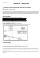
MECHANICAL INSTALLATION
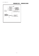
Fix the back of the box to the door. Install the transmitter following the technical manual and avoid placing metallic surfaces
between the receiver and the transmitter. Pass the cables through the bottom of the transmitter. Connect the safety edge
following the electrical connections clause and ensure that the safety edge keeps totally waterproof. Fix the front of the
transmitter to the back with the screws supplied for the purpose.
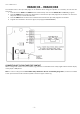
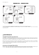
SELECTOR JUMPERS
Allow selecting the type of the security element which is connected.
Jumper selector Function
CS Voltage free safety contact
BS 8k2 monitored safety edge
O Opto safety edge
8k2 MONITORED SAFETY EDGE
Ensure the safety edge selection jumper is fitted in the BS position.
Electromechanical safety edges with 8k2 output are also considered 8k2 monitored safety edges.
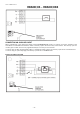
OPTO SAFETY EDGES
The use of opto safety edges requires the autotest signal or the current detector signal from the receiver.
Ensure the safety edge selection jumper is fitted in the O position.
The system is only compatible with low power opto transmitter/receiver (3Vdc / 3mA).
The opto safety edge remains in standby mode (non functioning) until it receives an activation signal from the receiver. The
activation signal is sent during the auto-test and it enables the opto safety edge for 60 seconds (by default) to allow the full
travel of the door/gate.
When using the current detector signal instead of autotest, the opto safety edge will remain active during the motor
movement.