
Installation Instructions
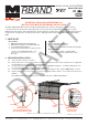

Miller Edge, Inc. • www.milleredge.com • info@milleredge.com • East Coast: 800-220-4422 • West Coast: 800-887-3343
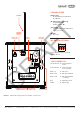
IMAGE 2. RBand Door Edge Receiver PCB & Connections
LED INDICATORS
Initial Power
• No Transmitters Programmed:
R1 LED on
R1 LED (1 edge connected)
• Programmed: Off
• Fault Condition: On
Check LED
• Programmed: Check LED flashes
every 5 seconds
R2 LED
• Not used
DIP SWITCH SETTINGS
ON
1 2 3
Leave switches in factory default
settings (all on).
7-PIN CONNECTOR
+12/24 VAC/DC Constant power
source
-12/24 VAC/DC Constant power
source ground
OSE1_3F Not used
OSE1_2FA P.E. input terminal
OSE1_2FB P.E. input terminal
or common
NC2 Normally closed
COM2 Open relay
ANT
R2
R1
CHECK
GND
PROG
ON
1 2 3
12/24
VAC/DC
OSE1_3F
+
-
NC2
COM2
OSE1_2FA
OSE1_2FB
MR
PROGRAM
BUTTON
CHECK LED
& BUTTON
REMOVABLE 7-PIN CONNECTOR DIP SWITCHES
RELAY
LEDS
ANTENNA
TERMINAL
BLOCK
ANTENNA
DRAFT