
OPERATOR'S MANUAL MAINTENANCE
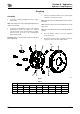

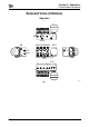
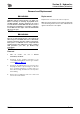
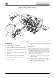
Table Of Contents
- A.pdf (p.1-99)
- 1.pdf (p.1)
- 2.pdf (p.2)
- 3.pdf (p.3)
- 4.pdf (p.4)
- 5.pdf (p.5)
- 6.pdf (p.6)
- 7.pdf (p.7)
- 8.pdf (p.8)
- 9.pdf (p.9)
- 10.pdf (p.10)
- 11.pdf (p.11)
- 12.pdf (p.12)
- 13.pdf (p.13)
- 14.pdf (p.14)
- 15.pdf (p.15)
- 16.pdf (p.16)
- 17.pdf (p.17)
- 18.pdf (p.18)
- 19.pdf (p.19)
- 20.pdf (p.20)
- 21.pdf (p.21)
- 22.pdf (p.22)
- 23.pdf (p.23)
- 24.pdf (p.24)
- 25.pdf (p.25)
- 26.pdf (p.26)
- 27.pdf (p.27)
- 28.pdf (p.28)
- 29.pdf (p.29)
- 30.pdf (p.30)
- 31.pdf (p.31)
- 32.pdf (p.32)
- 33.pdf (p.33)
- 34.pdf (p.34)
- 35.pdf (p.35)
- 36.pdf (p.36)
- 37.pdf (p.37)
- 38.pdf (p.38)
- 39.pdf (p.39)
- 40.pdf (p.40)
- 41.pdf (p.41)
- 42.pdf (p.42)
- 43.pdf (p.43)
- 44.pdf (p.44)
- 45.pdf (p.45)
- 46.pdf (p.46)
- 47.pdf (p.47)
- 48.pdf (p.48)
- 49.pdf (p.49)
- 50.pdf (p.50)
- 51.pdf (p.51)
- 52.pdf (p.52)
- 53.pdf (p.53)
- 54.pdf (p.54)
- 55.pdf (p.55)
- 56.pdf (p.56)
- 57.pdf (p.57)
- 58.pdf (p.58)
- 59.pdf (p.59)
- 60.pdf (p.60)
- 61.pdf (p.61)
- 62.pdf (p.62)
- 63.pdf (p.63)
- 64.pdf (p.64)
- 65.pdf (p.65)
- 66.pdf (p.66)
- 67.pdf (p.67)
- 68.pdf (p.68)
- 69.pdf (p.69)
- 70.pdf (p.70)
- 71.pdf (p.71)
- 72.pdf (p.72)
- 73.pdf (p.73)
- 74.pdf (p.74)
- 75.pdf (p.75)
- 76.pdf (p.76)
- 77.pdf (p.77)
- 78.pdf (p.78)
- 79.pdf (p.79)
- 80.pdf (p.80)
- 81.pdf (p.81)
- 82.pdf (p.82)
- 83.pdf (p.83)
- 84.pdf (p.84)
- 85.pdf (p.85)
- 86.pdf (p.86)
- 87.pdf (p.87)
- 88.pdf (p.88)
- 89.pdf (p.89)
- 90.pdf (p.90)
- 91.pdf (p.91)
- 92.pdf (p.92)
- 93.pdf (p.93)
- 94.pdf (p.94)
- 95.pdf (p.95)
- 96.pdf (p.96)
- 97.pdf (p.97)
- 98.pdf (p.98)
- 99.pdf (p.99)
- B.pdf (p.100-219)
- 1.pdf (p.1)
- 2.pdf (p.2)
- 3.pdf (p.3)
- 4.pdf (p.4)
- 5.pdf (p.5)
- 6.pdf (p.6)
- 7.pdf (p.7)
- 8.pdf (p.8)
- 9.pdf (p.9)
- 10.pdf (p.10)
- 11.pdf (p.11)
- 12.pdf (p.12)
- 13.pdf (p.13)
- 14.pdf (p.14)
- 15.pdf (p.15)
- 16.pdf (p.16)
- 17.pdf (p.17)
- 18.pdf (p.18)
- 19.pdf (p.19)
- 20.pdf (p.20)
- 21.pdf (p.21)
- 22.pdf (p.22)
- 23.pdf (p.23)
- 24.pdf (p.24)
- 25.pdf (p.25)
- 26.pdf (p.26)
- 27.pdf (p.27)
- 28.pdf (p.28)
- 29.pdf (p.29)
- 30.pdf (p.30)
- 31.pdf (p.31)
- 32.pdf (p.32)
- 33.pdf (p.33)
- 34.pdf (p.34)
- 35.pdf (p.35)
- 36.pdf (p.36)
- 37.pdf (p.37)
- 38.pdf (p.38)
- 39.pdf (p.39)
- 40.pdf (p.40)
- 41.pdf (p.41)
- 42.pdf (p.42)
- 43.pdf (p.43)
- 44.pdf (p.44)
- 45.pdf (p.45)
- 46.pdf (p.46)
- 47.pdf (p.47)
- 48.pdf (p.48)
- 49.pdf (p.49)
- 50.pdf (p.50)
- 51.pdf (p.51)
- 52.pdf (p.52)
- 53.pdf (p.53)
- 54.pdf (p.54)
- 55.pdf (p.55)
- 56.pdf (p.56)
- 57.pdf (p.57)
- 58.pdf (p.58)
- 59.pdf (p.59)
- 60.pdf (p.60)
- 61.pdf (p.61)
- 62.pdf (p.62)
- 63.pdf (p.63)
- 64.pdf (p.64)
- 65.pdf (p.65)
- 66.pdf (p.66)
- 67.pdf (p.67)
- 68.pdf (p.68)
- 69.pdf (p.69)
- 70.pdf (p.70)
- 71.pdf (p.71)
- 72.pdf (p.72)
- 73.pdf (p.73)
- 74.pdf (p.74)
- 75.pdf (p.75)
- 76.pdf (p.76)
- 77.pdf (p.77)
- 78.pdf (p.78)
- 79.pdf (p.79)
- 80.pdf (p.80)
- 81.pdf (p.81)
- 82.pdf (p.82)
- 83.pdf (p.83)
- 84.pdf (p.84)
- 85.pdf (p.85)
- 86.pdf (p.86)
- 87.pdf (p.87)
- 88.pdf (p.88)
- 89.pdf (p.89)
- 90.pdf (p.90)
- 91.pdf (p.91)
- 92.pdf (p.92)
- 93.pdf (p.93)
- 94.pdf (p.94)
- 95.pdf (p.95)
- 96.pdf (p.96)
- 97.pdf (p.97)
- 98.pdf (p.98)
- 99.pdf (p.99)
- 100.pdf (p.100)
- 101.pdf (p.101)
- 102.pdf (p.102)
- 103.pdf (p.103)
- 104.pdf (p.104)
- 105.pdf (p.105)
- 106.pdf (p.106)
- 107.pdf (p.107)
- 108.pdf (p.108)
- 109.pdf (p.109)
- 110.pdf (p.110)
- 111.pdf (p.111)
- 112.pdf (p.112)
- 113.pdf (p.113)
- 114.pdf (p.114)
- 115.pdf (p.115)
- 116.pdf (p.116)
- 117.pdf (p.117)
- 118.pdf (p.118)
- 119.pdf (p.119)
- 120.pdf (p.120)
- C.pdf (p.220-229)

Section E - Hydraulics
E-111 E-111
9803/9880-3
Travel Pedal Valve
Dismantling and Assembly
TE-007
Note: Parts can be damaged by use of excessive force.
Parts can be damaged by corrosion caused by humidity
and dust if left in un-assembled.
Note: For part number identification for the Travel Pedal
Valve,
K Fig 2. ( T E-112).
Dismantling
1 Clean the valve exterior using an de-greasing agent
and using soft metal pads for protection, clamp the
valve body into a vice.
2 Remove the gaiter 1 from the cover 2.
3 Loosen the 5mm hex screw 3.
!MWARNING
Always wear safety glasses when dismantling
assemblies containing components under pressure
from springs. This will protect against eye injury from
components accidentally flying out.
GEN-6-2
Note: Take care that push rod 4 does not fly out under
spring tension.
4 Remove pin 5 using a 7mm punch and remove cam
and steel balls 6.
Note: Take care that push rod 4 and plug 7 are not thrown
out by damping spring 8 pressure.
5 Loosen hex bolt 9 and remove cover. Making a note
of the relative positions of the cover 2 and the
casing 10. The plug 7 will remain in casing 10 due to
friction of the `O'-ring 11.
6 Remove casing 10 and fix in vice using soft metal
pads for protection.
7 Pull push rod 4 from plug 7 noting the relative
positions of plugs and push rods to the casing 10.
8 Remove plug 7 with the grease cap 12, packer 13 and
`O'-ring attached.
9 Remove piston 14 and damping spring 8 from the
casing.
10 Remove spring washer 16 from the casing 10 using
tweezers etc.
11 Remove steel balls 17 using a magnet.
12 Fix the lower casing assembly in a vice and remove
the `O'-rings 18, 19 from casing 20.
13 Remove pressure reduction valve assembly and
return spring 21 from casing 20.
14 Place cover 2 flat on a flat bench, apply special jig,
K
Fig 1. ( T E-111) to bush 23 and tap with a
hammer to remove the bush
A406320-1
Fig 1.
15 For disassembly of the pressure reduction valve,
press in spring washer 24, slide the spring washer
sideways, bending secondary pressure spring 25,
then remove spool 26 from the larger hole.
16 Separate spool 26, secondary pressure setting spring
25, shim 27 and washer 28.
A Central Hole (2mm maximum)
20
10mm
-0.3
-0.4
(A = 2 mm)
30mm
2
8mm
-0.2
-0.3
30
mm