
OPERATOR'S MANUAL MAINTENANCE
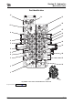
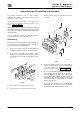
Table Of Contents
- A.pdf (p.1-99)
- 1.pdf (p.1)
- 2.pdf (p.2)
- 3.pdf (p.3)
- 4.pdf (p.4)
- 5.pdf (p.5)
- 6.pdf (p.6)
- 7.pdf (p.7)
- 8.pdf (p.8)
- 9.pdf (p.9)
- 10.pdf (p.10)
- 11.pdf (p.11)
- 12.pdf (p.12)
- 13.pdf (p.13)
- 14.pdf (p.14)
- 15.pdf (p.15)
- 16.pdf (p.16)
- 17.pdf (p.17)
- 18.pdf (p.18)
- 19.pdf (p.19)
- 20.pdf (p.20)
- 21.pdf (p.21)
- 22.pdf (p.22)
- 23.pdf (p.23)
- 24.pdf (p.24)
- 25.pdf (p.25)
- 26.pdf (p.26)
- 27.pdf (p.27)
- 28.pdf (p.28)
- 29.pdf (p.29)
- 30.pdf (p.30)
- 31.pdf (p.31)
- 32.pdf (p.32)
- 33.pdf (p.33)
- 34.pdf (p.34)
- 35.pdf (p.35)
- 36.pdf (p.36)
- 37.pdf (p.37)
- 38.pdf (p.38)
- 39.pdf (p.39)
- 40.pdf (p.40)
- 41.pdf (p.41)
- 42.pdf (p.42)
- 43.pdf (p.43)
- 44.pdf (p.44)
- 45.pdf (p.45)
- 46.pdf (p.46)
- 47.pdf (p.47)
- 48.pdf (p.48)
- 49.pdf (p.49)
- 50.pdf (p.50)
- 51.pdf (p.51)
- 52.pdf (p.52)
- 53.pdf (p.53)
- 54.pdf (p.54)
- 55.pdf (p.55)
- 56.pdf (p.56)
- 57.pdf (p.57)
- 58.pdf (p.58)
- 59.pdf (p.59)
- 60.pdf (p.60)
- 61.pdf (p.61)
- 62.pdf (p.62)
- 63.pdf (p.63)
- 64.pdf (p.64)
- 65.pdf (p.65)
- 66.pdf (p.66)
- 67.pdf (p.67)
- 68.pdf (p.68)
- 69.pdf (p.69)
- 70.pdf (p.70)
- 71.pdf (p.71)
- 72.pdf (p.72)
- 73.pdf (p.73)
- 74.pdf (p.74)
- 75.pdf (p.75)
- 76.pdf (p.76)
- 77.pdf (p.77)
- 78.pdf (p.78)
- 79.pdf (p.79)
- 80.pdf (p.80)
- 81.pdf (p.81)
- 82.pdf (p.82)
- 83.pdf (p.83)
- 84.pdf (p.84)
- 85.pdf (p.85)
- 86.pdf (p.86)
- 87.pdf (p.87)
- 88.pdf (p.88)
- 89.pdf (p.89)
- 90.pdf (p.90)
- 91.pdf (p.91)
- 92.pdf (p.92)
- 93.pdf (p.93)
- 94.pdf (p.94)
- 95.pdf (p.95)
- 96.pdf (p.96)
- 97.pdf (p.97)
- 98.pdf (p.98)
- 99.pdf (p.99)
- B.pdf (p.100-219)
- 1.pdf (p.1)
- 2.pdf (p.2)
- 3.pdf (p.3)
- 4.pdf (p.4)
- 5.pdf (p.5)
- 6.pdf (p.6)
- 7.pdf (p.7)
- 8.pdf (p.8)
- 9.pdf (p.9)
- 10.pdf (p.10)
- 11.pdf (p.11)
- 12.pdf (p.12)
- 13.pdf (p.13)
- 14.pdf (p.14)
- 15.pdf (p.15)
- 16.pdf (p.16)
- 17.pdf (p.17)
- 18.pdf (p.18)
- 19.pdf (p.19)
- 20.pdf (p.20)
- 21.pdf (p.21)
- 22.pdf (p.22)
- 23.pdf (p.23)
- 24.pdf (p.24)
- 25.pdf (p.25)
- 26.pdf (p.26)
- 27.pdf (p.27)
- 28.pdf (p.28)
- 29.pdf (p.29)
- 30.pdf (p.30)
- 31.pdf (p.31)
- 32.pdf (p.32)
- 33.pdf (p.33)
- 34.pdf (p.34)
- 35.pdf (p.35)
- 36.pdf (p.36)
- 37.pdf (p.37)
- 38.pdf (p.38)
- 39.pdf (p.39)
- 40.pdf (p.40)
- 41.pdf (p.41)
- 42.pdf (p.42)
- 43.pdf (p.43)
- 44.pdf (p.44)
- 45.pdf (p.45)
- 46.pdf (p.46)
- 47.pdf (p.47)
- 48.pdf (p.48)
- 49.pdf (p.49)
- 50.pdf (p.50)
- 51.pdf (p.51)
- 52.pdf (p.52)
- 53.pdf (p.53)
- 54.pdf (p.54)
- 55.pdf (p.55)
- 56.pdf (p.56)
- 57.pdf (p.57)
- 58.pdf (p.58)
- 59.pdf (p.59)
- 60.pdf (p.60)
- 61.pdf (p.61)
- 62.pdf (p.62)
- 63.pdf (p.63)
- 64.pdf (p.64)
- 65.pdf (p.65)
- 66.pdf (p.66)
- 67.pdf (p.67)
- 68.pdf (p.68)
- 69.pdf (p.69)
- 70.pdf (p.70)
- 71.pdf (p.71)
- 72.pdf (p.72)
- 73.pdf (p.73)
- 74.pdf (p.74)
- 75.pdf (p.75)
- 76.pdf (p.76)
- 77.pdf (p.77)
- 78.pdf (p.78)
- 79.pdf (p.79)
- 80.pdf (p.80)
- 81.pdf (p.81)
- 82.pdf (p.82)
- 83.pdf (p.83)
- 84.pdf (p.84)
- 85.pdf (p.85)
- 86.pdf (p.86)
- 87.pdf (p.87)
- 88.pdf (p.88)
- 89.pdf (p.89)
- 90.pdf (p.90)
- 91.pdf (p.91)
- 92.pdf (p.92)
- 93.pdf (p.93)
- 94.pdf (p.94)
- 95.pdf (p.95)
- 96.pdf (p.96)
- 97.pdf (p.97)
- 98.pdf (p.98)
- 99.pdf (p.99)
- 100.pdf (p.100)
- 101.pdf (p.101)
- 102.pdf (p.102)
- 103.pdf (p.103)
- 104.pdf (p.104)
- 105.pdf (p.105)
- 106.pdf (p.106)
- 107.pdf (p.107)
- 108.pdf (p.108)
- 109.pdf (p.109)
- 110.pdf (p.110)
- 111.pdf (p.111)
- 112.pdf (p.112)
- 113.pdf (p.113)
- 114.pdf (p.114)
- 115.pdf (p.115)
- 116.pdf (p.116)
- 117.pdf (p.117)
- 118.pdf (p.118)
- 119.pdf (p.119)
- 120.pdf (p.120)
- C.pdf (p.220-229)

Section E - Hydraulics
E-75 E-75
9803/9880-3
Hydraulic Pump/Regulator
Hydraulic Pump Operation
Hydraulic Pump Regulation
For this description pump A2 has been used. For
schematic,
K Fig 1. ( T E-17)
On start up, the swash plate piston F is held in the
maximum flow position by the spring A.
Once oil as passed through the valve block a 37 bar (537
Ib in
2
) negative control signal enters port Pi2 and is
available to the negative control piston D. This acts against
spring A to move the spool across allowing pump pressure
to cross the spool and pressurise the large diameter side
of the swash plate piston F. Pressure is now available to
both sides of the swash piston F, but due to the difference
in surface areas the piston moves to the minimum flow
position.
When a service is selected the negative control pressure
drops. Piston D now moves back due to the spring
pressure. This allows the oil in the larger area side of the
swash plate piston F to vent to tank, but pump pressure oil
is still available to the smaller diameter side so the pump
moves over to the maximum flow position.
As the pump pressure increases, the pressure seen at the
small diameter end of the swash plate piston F is also seen
at the piston C. At the same time any pressure generated
at pump A1 is also seen at pump A2 at the piston C. As the
pressure increases at piston C via line B it starts to push
against spring A. When the pressure has increased to
approximately 200 bar (2900Ib in
2
) the spool will start to
select. This will now allow pump pressure to the large
diameter side of the swash plate piston F which will
proportionally start to select minimum flow.
When L mode is selected a 40 bar (580 Ib in
2
) signal from
the Max flow cut solenoid on the 8 spool solenoid is sent to
Pm2 of the pump. This prevents the pump from selecting
100% flow and limits it to 60% flow.
In A mode the secondary pressure drops to approximately
10 bar (145Ib in
2
). This reduction in secondary pressure at
piston D has to be made up for by higher pump pressure
at pistons C and E before the Sumater spool starts to
select, hence more hydraulic horsepower.
The regulator on pump A1 works the same as above.
If Q max cut is selected a 40 bar servo pressure signal
from the 8 spool solenoid block enters the pump at port
Pm2. This will partly select the Q max cut piston J. which
pushed the piston against spring A and reduces the pump
to 60% maximum flow.