
OPERATOR'S MANUAL MAINTENANCE
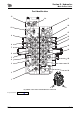
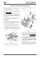
Table Of Contents
- A.pdf (p.1-99)
- 1.pdf (p.1)
- 2.pdf (p.2)
- 3.pdf (p.3)
- 4.pdf (p.4)
- 5.pdf (p.5)
- 6.pdf (p.6)
- 7.pdf (p.7)
- 8.pdf (p.8)
- 9.pdf (p.9)
- 10.pdf (p.10)
- 11.pdf (p.11)
- 12.pdf (p.12)
- 13.pdf (p.13)
- 14.pdf (p.14)
- 15.pdf (p.15)
- 16.pdf (p.16)
- 17.pdf (p.17)
- 18.pdf (p.18)
- 19.pdf (p.19)
- 20.pdf (p.20)
- 21.pdf (p.21)
- 22.pdf (p.22)
- 23.pdf (p.23)
- 24.pdf (p.24)
- 25.pdf (p.25)
- 26.pdf (p.26)
- 27.pdf (p.27)
- 28.pdf (p.28)
- 29.pdf (p.29)
- 30.pdf (p.30)
- 31.pdf (p.31)
- 32.pdf (p.32)
- 33.pdf (p.33)
- 34.pdf (p.34)
- 35.pdf (p.35)
- 36.pdf (p.36)
- 37.pdf (p.37)
- 38.pdf (p.38)
- 39.pdf (p.39)
- 40.pdf (p.40)
- 41.pdf (p.41)
- 42.pdf (p.42)
- 43.pdf (p.43)
- 44.pdf (p.44)
- 45.pdf (p.45)
- 46.pdf (p.46)
- 47.pdf (p.47)
- 48.pdf (p.48)
- 49.pdf (p.49)
- 50.pdf (p.50)
- 51.pdf (p.51)
- 52.pdf (p.52)
- 53.pdf (p.53)
- 54.pdf (p.54)
- 55.pdf (p.55)
- 56.pdf (p.56)
- 57.pdf (p.57)
- 58.pdf (p.58)
- 59.pdf (p.59)
- 60.pdf (p.60)
- 61.pdf (p.61)
- 62.pdf (p.62)
- 63.pdf (p.63)
- 64.pdf (p.64)
- 65.pdf (p.65)
- 66.pdf (p.66)
- 67.pdf (p.67)
- 68.pdf (p.68)
- 69.pdf (p.69)
- 70.pdf (p.70)
- 71.pdf (p.71)
- 72.pdf (p.72)
- 73.pdf (p.73)
- 74.pdf (p.74)
- 75.pdf (p.75)
- 76.pdf (p.76)
- 77.pdf (p.77)
- 78.pdf (p.78)
- 79.pdf (p.79)
- 80.pdf (p.80)
- 81.pdf (p.81)
- 82.pdf (p.82)
- 83.pdf (p.83)
- 84.pdf (p.84)
- 85.pdf (p.85)
- 86.pdf (p.86)
- 87.pdf (p.87)
- 88.pdf (p.88)
- 89.pdf (p.89)
- 90.pdf (p.90)
- 91.pdf (p.91)
- 92.pdf (p.92)
- 93.pdf (p.93)
- 94.pdf (p.94)
- 95.pdf (p.95)
- 96.pdf (p.96)
- 97.pdf (p.97)
- 98.pdf (p.98)
- 99.pdf (p.99)
- B.pdf (p.100-219)
- 1.pdf (p.1)
- 2.pdf (p.2)
- 3.pdf (p.3)
- 4.pdf (p.4)
- 5.pdf (p.5)
- 6.pdf (p.6)
- 7.pdf (p.7)
- 8.pdf (p.8)
- 9.pdf (p.9)
- 10.pdf (p.10)
- 11.pdf (p.11)
- 12.pdf (p.12)
- 13.pdf (p.13)
- 14.pdf (p.14)
- 15.pdf (p.15)
- 16.pdf (p.16)
- 17.pdf (p.17)
- 18.pdf (p.18)
- 19.pdf (p.19)
- 20.pdf (p.20)
- 21.pdf (p.21)
- 22.pdf (p.22)
- 23.pdf (p.23)
- 24.pdf (p.24)
- 25.pdf (p.25)
- 26.pdf (p.26)
- 27.pdf (p.27)
- 28.pdf (p.28)
- 29.pdf (p.29)
- 30.pdf (p.30)
- 31.pdf (p.31)
- 32.pdf (p.32)
- 33.pdf (p.33)
- 34.pdf (p.34)
- 35.pdf (p.35)
- 36.pdf (p.36)
- 37.pdf (p.37)
- 38.pdf (p.38)
- 39.pdf (p.39)
- 40.pdf (p.40)
- 41.pdf (p.41)
- 42.pdf (p.42)
- 43.pdf (p.43)
- 44.pdf (p.44)
- 45.pdf (p.45)
- 46.pdf (p.46)
- 47.pdf (p.47)
- 48.pdf (p.48)
- 49.pdf (p.49)
- 50.pdf (p.50)
- 51.pdf (p.51)
- 52.pdf (p.52)
- 53.pdf (p.53)
- 54.pdf (p.54)
- 55.pdf (p.55)
- 56.pdf (p.56)
- 57.pdf (p.57)
- 58.pdf (p.58)
- 59.pdf (p.59)
- 60.pdf (p.60)
- 61.pdf (p.61)
- 62.pdf (p.62)
- 63.pdf (p.63)
- 64.pdf (p.64)
- 65.pdf (p.65)
- 66.pdf (p.66)
- 67.pdf (p.67)
- 68.pdf (p.68)
- 69.pdf (p.69)
- 70.pdf (p.70)
- 71.pdf (p.71)
- 72.pdf (p.72)
- 73.pdf (p.73)
- 74.pdf (p.74)
- 75.pdf (p.75)
- 76.pdf (p.76)
- 77.pdf (p.77)
- 78.pdf (p.78)
- 79.pdf (p.79)
- 80.pdf (p.80)
- 81.pdf (p.81)
- 82.pdf (p.82)
- 83.pdf (p.83)
- 84.pdf (p.84)
- 85.pdf (p.85)
- 86.pdf (p.86)
- 87.pdf (p.87)
- 88.pdf (p.88)
- 89.pdf (p.89)
- 90.pdf (p.90)
- 91.pdf (p.91)
- 92.pdf (p.92)
- 93.pdf (p.93)
- 94.pdf (p.94)
- 95.pdf (p.95)
- 96.pdf (p.96)
- 97.pdf (p.97)
- 98.pdf (p.98)
- 99.pdf (p.99)
- 100.pdf (p.100)
- 101.pdf (p.101)
- 102.pdf (p.102)
- 103.pdf (p.103)
- 104.pdf (p.104)
- 105.pdf (p.105)
- 106.pdf (p.106)
- 107.pdf (p.107)
- 108.pdf (p.108)
- 109.pdf (p.109)
- 110.pdf (p.110)
- 111.pdf (p.111)
- 112.pdf (p.112)
- 113.pdf (p.113)
- 114.pdf (p.114)
- 115.pdf (p.115)
- 116.pdf (p.116)
- 117.pdf (p.117)
- 118.pdf (p.118)
- 119.pdf (p.119)
- 120.pdf (p.120)
- C.pdf (p.220-229)

Section E - Hydraulics
Circuit Descriptions
Slew Circuit
E-50 E-50
9803/9880-3
Slew Circuit
For schematic,
K Fig 18. ( T E-51).
Circuit description is for swing left.
Servo pressure from the hand controller 50 enters the
Servo shuttle valve 46 at port A2 and is distributed to:
1 Port C7 to port A on 8 station solenoid valve 60.
2 Port C8 to port Pc3 in main control valve to the slew
over dipper priority spool SDV.
3 Port S1 to the slew pressure switch 45.
4 Port B2 via the slew shut off solenoid 44 to the slew
spool at port Pa3 on the main control valve 14 to
move spool across.
When the pressure switch 45 closes, a signal is sent from
the ECU1 to energise CT1 on the 8 station solenoid valve
60. This allows 40 bar (580 lb/in
2
) to cross the solenoid
then cross the shuttle CT10 and the slew lock solenoid
CT3 to release the slew brake.
When the slew pressure switch 45 opens, the solenoid
remains energised for 5 seconds to allow the slew to come
to a standstill before the brake is applied. If the pressure
switch fails, there is an override device fitted. Servo
pressure from the hand controller 50 passes through the
shuttle valve 46 and exits at C7. This signal is sent to the
8 station solenoid valve 60 to port A, crosses the shuttle
CT10 and the slew lock solenoid CT3 and releases the
slew brake.
Note: When the override is in operation, the slew may
become very harsh.
Flow from pump 2 travels through the neutral gallery to the
slew spool. The flow is restricted allowing reduced
pressure at port ps1 which is sensed at pm2 of pump 2
allowing the pump to come to full flow. The flow passes
through into the parallel working passage to the slew
spool. The flow is then directed via port A3 to the slew
motor 1. Exhaust oil enters the main control valve 14 at B3
through the slew spool to the tank line.
Slew over Dipper Priority (A)
This is a non-selectable function automatically carried out
within the main control valve 14 when slew and dipper are
used together.
When slew is selected a signal is sent from the servo
shuttle valve 46 via port C8 to the main control valve 14 at
port Pc3. This selects slew over dipper priority valve B and
limits the flow to the dipper from pump A2 only. This makes
it possible to have maximum slew torque with high slew
pressure when the dipper is used at the same time.