
OPERATOR'S MANUAL MAINTENANCE
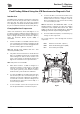

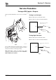
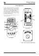


Table Of Contents
- A.pdf (p.1-99)
- 1.pdf (p.1)
- 2.pdf (p.2)
- 3.pdf (p.3)
- 4.pdf (p.4)
- 5.pdf (p.5)
- 6.pdf (p.6)
- 7.pdf (p.7)
- 8.pdf (p.8)
- 9.pdf (p.9)
- 10.pdf (p.10)
- 11.pdf (p.11)
- 12.pdf (p.12)
- 13.pdf (p.13)
- 14.pdf (p.14)
- 15.pdf (p.15)
- 16.pdf (p.16)
- 17.pdf (p.17)
- 18.pdf (p.18)
- 19.pdf (p.19)
- 20.pdf (p.20)
- 21.pdf (p.21)
- 22.pdf (p.22)
- 23.pdf (p.23)
- 24.pdf (p.24)
- 25.pdf (p.25)
- 26.pdf (p.26)
- 27.pdf (p.27)
- 28.pdf (p.28)
- 29.pdf (p.29)
- 30.pdf (p.30)
- 31.pdf (p.31)
- 32.pdf (p.32)
- 33.pdf (p.33)
- 34.pdf (p.34)
- 35.pdf (p.35)
- 36.pdf (p.36)
- 37.pdf (p.37)
- 38.pdf (p.38)
- 39.pdf (p.39)
- 40.pdf (p.40)
- 41.pdf (p.41)
- 42.pdf (p.42)
- 43.pdf (p.43)
- 44.pdf (p.44)
- 45.pdf (p.45)
- 46.pdf (p.46)
- 47.pdf (p.47)
- 48.pdf (p.48)
- 49.pdf (p.49)
- 50.pdf (p.50)
- 51.pdf (p.51)
- 52.pdf (p.52)
- 53.pdf (p.53)
- 54.pdf (p.54)
- 55.pdf (p.55)
- 56.pdf (p.56)
- 57.pdf (p.57)
- 58.pdf (p.58)
- 59.pdf (p.59)
- 60.pdf (p.60)
- 61.pdf (p.61)
- 62.pdf (p.62)
- 63.pdf (p.63)
- 64.pdf (p.64)
- 65.pdf (p.65)
- 66.pdf (p.66)
- 67.pdf (p.67)
- 68.pdf (p.68)
- 69.pdf (p.69)
- 70.pdf (p.70)
- 71.pdf (p.71)
- 72.pdf (p.72)
- 73.pdf (p.73)
- 74.pdf (p.74)
- 75.pdf (p.75)
- 76.pdf (p.76)
- 77.pdf (p.77)
- 78.pdf (p.78)
- 79.pdf (p.79)
- 80.pdf (p.80)
- 81.pdf (p.81)
- 82.pdf (p.82)
- 83.pdf (p.83)
- 84.pdf (p.84)
- 85.pdf (p.85)
- 86.pdf (p.86)
- 87.pdf (p.87)
- 88.pdf (p.88)
- 89.pdf (p.89)
- 90.pdf (p.90)
- 91.pdf (p.91)
- 92.pdf (p.92)
- 93.pdf (p.93)
- 94.pdf (p.94)
- 95.pdf (p.95)
- 96.pdf (p.96)
- 97.pdf (p.97)
- 98.pdf (p.98)
- 99.pdf (p.99)
- B.pdf (p.100-219)
- 1.pdf (p.1)
- 2.pdf (p.2)
- 3.pdf (p.3)
- 4.pdf (p.4)
- 5.pdf (p.5)
- 6.pdf (p.6)
- 7.pdf (p.7)
- 8.pdf (p.8)
- 9.pdf (p.9)
- 10.pdf (p.10)
- 11.pdf (p.11)
- 12.pdf (p.12)
- 13.pdf (p.13)
- 14.pdf (p.14)
- 15.pdf (p.15)
- 16.pdf (p.16)
- 17.pdf (p.17)
- 18.pdf (p.18)
- 19.pdf (p.19)
- 20.pdf (p.20)
- 21.pdf (p.21)
- 22.pdf (p.22)
- 23.pdf (p.23)
- 24.pdf (p.24)
- 25.pdf (p.25)
- 26.pdf (p.26)
- 27.pdf (p.27)
- 28.pdf (p.28)
- 29.pdf (p.29)
- 30.pdf (p.30)
- 31.pdf (p.31)
- 32.pdf (p.32)
- 33.pdf (p.33)
- 34.pdf (p.34)
- 35.pdf (p.35)
- 36.pdf (p.36)
- 37.pdf (p.37)
- 38.pdf (p.38)
- 39.pdf (p.39)
- 40.pdf (p.40)
- 41.pdf (p.41)
- 42.pdf (p.42)
- 43.pdf (p.43)
- 44.pdf (p.44)
- 45.pdf (p.45)
- 46.pdf (p.46)
- 47.pdf (p.47)
- 48.pdf (p.48)
- 49.pdf (p.49)
- 50.pdf (p.50)
- 51.pdf (p.51)
- 52.pdf (p.52)
- 53.pdf (p.53)
- 54.pdf (p.54)
- 55.pdf (p.55)
- 56.pdf (p.56)
- 57.pdf (p.57)
- 58.pdf (p.58)
- 59.pdf (p.59)
- 60.pdf (p.60)
- 61.pdf (p.61)
- 62.pdf (p.62)
- 63.pdf (p.63)
- 64.pdf (p.64)
- 65.pdf (p.65)
- 66.pdf (p.66)
- 67.pdf (p.67)
- 68.pdf (p.68)
- 69.pdf (p.69)
- 70.pdf (p.70)
- 71.pdf (p.71)
- 72.pdf (p.72)
- 73.pdf (p.73)
- 74.pdf (p.74)
- 75.pdf (p.75)
- 76.pdf (p.76)
- 77.pdf (p.77)
- 78.pdf (p.78)
- 79.pdf (p.79)
- 80.pdf (p.80)
- 81.pdf (p.81)
- 82.pdf (p.82)
- 83.pdf (p.83)
- 84.pdf (p.84)
- 85.pdf (p.85)
- 86.pdf (p.86)
- 87.pdf (p.87)
- 88.pdf (p.88)
- 89.pdf (p.89)
- 90.pdf (p.90)
- 91.pdf (p.91)
- 92.pdf (p.92)
- 93.pdf (p.93)
- 94.pdf (p.94)
- 95.pdf (p.95)
- 96.pdf (p.96)
- 97.pdf (p.97)
- 98.pdf (p.98)
- 99.pdf (p.99)
- 100.pdf (p.100)
- 101.pdf (p.101)
- 102.pdf (p.102)
- 103.pdf (p.103)
- 104.pdf (p.104)
- 105.pdf (p.105)
- 106.pdf (p.106)
- 107.pdf (p.107)
- 108.pdf (p.108)
- 109.pdf (p.109)
- 110.pdf (p.110)
- 111.pdf (p.111)
- 112.pdf (p.112)
- 113.pdf (p.113)
- 114.pdf (p.114)
- 115.pdf (p.115)
- 116.pdf (p.116)
- 117.pdf (p.117)
- 118.pdf (p.118)
- 119.pdf (p.119)
- 120.pdf (p.120)
- C.pdf (p.220-229)

Section C - Electrics
Harness Data
Harness Interconnection
C-177 C-177
9803/9880-3
Harness Data
Harness Interconnection
Fig 1. Harness Location and Interconnection (Type 2 Fascia Harness and Type C Cab Harness Shown)
Cab Sub Harness -
Main component s connected
to this harness:
Roof
Facia Link Harness -
Main component s
connected to this
harness:
Elect ronic Monit oring
System (EMS)
Power Socket
Radio Mut e Switch
Facia Switch Panel
HVAC Controller
Main Harness -
Main component s
connected to this
harness:
Slew Brake Valve
Main Control Valve
8 Spool Solenoid -
Shuttle Valve
Fuse link - Ignition
Battery
Glow Plugs
Alt ernator
Starter Motor
Engine
Temperature - Sensors
Work Light s
Cab Harness -
Main component s
connected to this
harness:
Elect ronic Control
ECU1
ECM
Fuses
Voltage Converter
Diagnostic Connector
Wiper motors
Control Lever Switches
Ignit ion Switch
Thrott le Dial
Int erior Light Sw itch