Surround Cinema Series Models: SCS150SI SCS160SI SCS180.6S Home Theater Speaker Systems SERVICE MANUAL JBL Consumer Products 250 Crossways Park Dr.
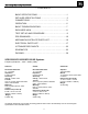
SCS150SI/SCS160SI/SCS180.6S - CONTENTS BASIC SPECIFICATIONS……………….……….……………….1 DETAILED SPECIFICATIONS ……..………………..…………..2 CONNECTIONS…………… …..……………...…………..……...3 OPERATION………………………………………………………. 6 BASIC TROUBLESHOOTING……..……….…………………….7 EXPLODED VIEW……..……….………………………………….8 TEST SET-UP AND PROCEDURE……..……….………..……..9 PCB DRAWINGS…………… ……..………………..…….……..10 MECHANICAL/SATELLITE PARTS LIST………………………16 ELECTRICAL PARTS LIST ……………....……………….…….17 IC/TRANSISTOR PINOUTS……..…….…………………..…….
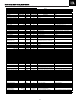
SCS150SI/SCS160SI/SCS180.6S 150W Powered Sub/ Plate Amp LINE VOLTAGE US 120vac/60Hz Asia 100vac/50Hz Parameter Amp Section Type (Class AB, D, other) Load Impedance (speaker) Rated Output Power THD@ Rated Power THD @ 1 Watt DC Offset Damping factor Yes/No Yes Yes Hi/Lo Line Unit 108-132 Vrms 90-110 Vrms Specification Unit D 4 150 0.08 0.
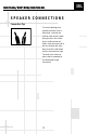
SCS150SI/SCS160SI/SCS180.6S SPEAKER CONNECTIONS Connection Tips To use the binding-post speaker terminals on the subwoofer, unscrew the colored collar until the pass through hole in the center post is visible under the collar. Insert the bare end of the wire through this hole; then screw the collar down until the connection is tight. The hole in the center of each collar is intended for use with banana-type connectors.
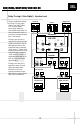
SCS150SI/SCS160SI/SCS180.6S Dolby* Pro Logic* (Non-Digital) – Speaker Level Use this installation method for Dolby Pro Logic applications (not Dolby Digital, DTS® or other digital processing), where the receiver/processor does not have a subwoofer output, or a volume-controlled preamp (line-) level output: Connect your receiver or amplifier’s front left and right speaker terminals to the left and right terminals on the subwoofer that are marked “High Level In.
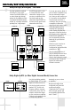
SCS150SI/SCS160SI/SCS180.6S Dolby Pro Logic (Non-Digital) – Line Level Use this installation method for Dolby Pro Logic applications (not Dolby Digital, DTS or other digital processing), where the receiver/processor is equipped with a subwoofer output, or a volume-controlled preamp (line-) level output: Use RCA-type patch cords to connect the line-level subwoofer outputs on your receiver or amplifier to the line-level inputs on the subwoofer.
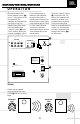
SCS150SI/SCS160SI/SCS180.6S O P E R AT I O N Move the Master Power switch (marked “Power” ¡) to the “•” (On) position to use the subwoofer. The subwoofer will automatically turn itself on or go into standby (sleep) mode when left in the standby mode (“Auto/On” switch ™ in the “Auto” position). When your receiver or amplifier is off, or HIGH LEVEL + L – – R + is not sending program material to the subwoofer, the subwoofer will be in standby mode.
SCS150SI/SCS160SI/SCS180.6S TROUBLESHOOTING If there is no sound from any of the speakers: • Check that receiver/amplifier is on and a source is playing. • Check that the powered subwoofer is plugged in, and its Power switch ¡ is switched on to the “•” position. • Check all wires and connections between receiver/ amplifier and speakers. Make sure all wires are connected. Make sure none of the speaker wires are frayed, cut or punctured. • Review proper operation of your receiver/amplifier.
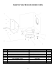
SUB150/160/180 EXPLODED VIEW Ref# Description Part Number Qty 1 2 SUB150/160/180 CABINET FOOT – MAIN PLASTIC BODY “ “ FOOT – RUBBER BOTTOM “ FOOT SCREW T4*30L 10” WOOFER AMPLIFIER/WOOFER SCREWS T4*20L SUB150/160/180 AMPLIFIER NOT FOR SALE (SCS150SI) WI5447 (SCS160SI) 321-ABS-00008 (SCS180.6) 321-ABS-00008-0LA (SCS150SI) WI5448 (SCS160SI/180.
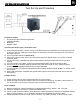
SCS150SI/SCS160SI/SCS180.6S Test Set Up and Procedure Equipment needed: • Function/signal generator/sweep generator • Integrated Amplifier • Multimeter • Speaker cables General Unit Function (UUT = Unit Under Test) 1) From the signal generator, connect one line level (RCA) cable to the Subwoofer Line Level Input jacks L/R on the UUT. Use a Y-cable from a mono source if necessary to connect to both inputs. Do not connect to the single LFE input. 2) Turn on generator; adjust to 100mV, 50 Hz.
SCS150SI/SCS160SI/SCS180.
SCS150SI/SCS160SI/SCS180.
SCS150SI/SCS160SI/SCS180.
SCS150SI/SCS160SI/SCS180.
SCS150SI/SCS160SI/SCS180.
SCS150SI/SCS160SI/SCS180.
SCS150SI/SCS160SI/SCS180.6S Mechanical/Satellite Parts List SCS150SI SCS160SI SCS180.
SCS150SI/SCS160SI/SCS180.6S SUB150/SUB160/SUB180 Electrical parts List Part# Reference Designator Description Qty Input/Power Amp PCB Semiconductors 197131n4148 D102,103,104,105,143,201-208, 211,212,214,215,216,301,302 D213 D101 D502 Q108,109,113,201,206-208,301,302 Q111 Q101,107,112 Q114,115 Q503 U203 U201,202,301 Q501 Q502 D209 D501 D110,504 Diode 1N4148 20 Zener 3.3V 1/2W 52mm TAP Zener 6.2V 1/2W 52mm TAP Zener 16V 1/2W 52mm TAP Trans NPN 60V .15A 2SC1815GR Trans NPN 120V 0.
SCS150SI/SCS160SI/SCS180.
SCS150SI/SCS160SI/SCS180.6S Part# Reference Designator Description Qty CAP, E 1U 50V ±20% TAP CAP, E 10U 50V ±20% TAP 1 12 CAP, E CAP, E CAP, E CAP, E CAP, E CAP, E CAP, E CAP, E 2 1 2 1 1 3 2 1 Input/Power Amp PCB 1353105m50 1353106m50 1353107m10 1353107m16 1353107m35 1353225m50 1353226m16 1353226m50 1353227m16 1353476m16 C228 C201,202,206,213,219,231,241,243, 251,253,319,321 C114,115 C234 C507,508 C509 C304 C225,505,506 C118,233 C318 100U 10V ±20% TAP 100uF 16V ±20% TAP 100U 35V ±20% TAP 2.
SCS150SI/SCS160SI/SCS180.6S Part# Reference Designator Description Qty Power Amp Class D Module part# 012-7500-00022 RECOMMENDED: REPLACE ENTIRE MODULE Semiconductors 19016tl072dts 19209124126qs 19209139066rs 19209210376qs 19209215146rs 19703rls4148s 19915000563s 19915001203s 19915001503s 192232irf9640 192233irf640 IC1 Q1,4,5 Q2,8 Q7,9 Q3,6 D1,2,3,4,5,6 Z1,2 Z5,6 Z3,4 Q10 Q11 SMD I.C. TL072CDT SGS Dual Op-Amp TRANS, NPN 50V 0.15A 2SC2412K TRANS, NPN 120V 0.05A 2SC3906K TRANS, PNP 50V 0.
SCS150SI/SCS160SI/SCS180.6S Part# Reference Designator Description Qty Misc./Mechanical 723a125 723a125-1 723b125 723b125-1 723j125 06-t30804 06-t31004 06-t41208 104ds15000 104sub15000 16210060003 16210082007 16250129001 1740rca108gb 1740rcb202vg 17420810360g 1751c07v01 1751d02v01 1751d03v01 193201815t2 1201000003 EVA (Gasket) 213*15*2.0mm EVA (Gasket) 213*15*1.0t EVA (Gasket) 238*15*2.0mm EVA (Gasket) 238*15*1.
SCS150SI/SCS160SI/SCS180.6S Integrated Circuit Diagrams OPAMP, QUAD 14P DIL TL074 U201, 202, 301 4558 / TLO72 DUAL OP AMP, U203, IC1 MOSFET, TO220 IRF640, 9640 Q11, 10 TIP31C NPN, TIP32C PNP, Q501,502 1. G 2. D 3.
SCHEMATICS SCS150SI/SCS160SI/SCS180.
SCS150SI/SCS160SI/SCS180.
SCS150SI/SCS160SI/SCS180.
SCS150SI/SCS160SI/SCS180.6S Packaging WIRE SET (SURROUND) SCS150SI – SAL5009 SCS160SI/SCS180.6S – 370-000-00081 SATELLITE STYROFOAM SCS160SI/SCS180.6S – 431-000-00937 WIRE SET (SATS & CENTER) SCS150SI – SAL5019 SCS160SI/SCS180.6S – 370-000-00087 SUPPORT MURAL SCS150SI – WI0409 SCS160SI/SCS180.6S – 325-FE-00163 WIRE SET (SUB IN/OUT) SCS150SI – SAL063-1 SCS160SI/SCS180.6S – 370-000-00069 WALL BRACKET SCS150SI – WI0408 SCS160SI/SCS180.6S – 372-000-00042 WARRANTY CARD SCS150SI – AT5160 SCS160SI/SCS180.