A Loudspeaker With Intelligence User’s Guide Introducing The Next Generation of Installed Sound
EVOi.net C O N T E N T S Safety Information . . . . . . . . . . . . . . . . . . . . . 1 Introduction . . . . . . . . . . . . . . . . . . . . . . . . . . 2 Design Overview . . . . . . . . . . . . . . . . . . . . . . 3 Features EVOi.net Front ............................... EVOi.net Rear . . . . . . . . . . . . . . . . . . . . . . . . . . . . . . . . . . . 4 6 Installation / Setup. . . . . . . . . . . . . . . . . . . . . . 7 Measurement Microphone . . . . . . . . . . . . . . . . . . . . . . . .
IMPORTANT SAFETY INFORMATION - READ THIS CAREFULLY This equipment has been tested and found to comply with the following European and international standards for Electromagnetic Compatibility and Electrical Safety: Radiated Emmissions (EU): EN55022B (1992) RF Immunity (EU): IEC801-3 (1994) Electrostatic Discharge(EU): IEC801-2 (1984) Fast Transients(EU): IEC801-4 (1988) Electrical Safety (EU): EN60065 (1994) Electrical Safety(USA): UL6500/ETL (1996) Electrical Safety(CAN): CAN/CSA-E65/ETLc (1996) Before usi
I N T R O D U C T I O N WELCOME Thank you for purchasing an EVOi.net Speaker System Controller or, if you have been referred to this section via EVOi.sys, thank you for purchasing an EVOi.sys. As part of EVO Systems, the EVOi.net provides simple to understand yet flexible access to the full functionality of EVO Intelligent Loudspeaker Systems. We like to say the EVOi.net accesses the intelligence. PACKAGE CONTENTS Upon unpacking the EVOi.net please take note of the contents as listed below.
D E S I G N O V E R V I E W The EVOi.net is either supplied in a 19” rack mount configuration or as part of the EVOi.sys. Simplicity in the presentation is at the forefront of the EVOi.net design. For installed loudspeaker systems, it is not practical to initiate setup and operational function with control on the actual loudspeakers. Therefore the EVOi.net simply provides a more convenient remote control of the functions in the EVO Intelligent Loudspeaker Systems.
F E A T U R E S FRONT PANEL Figure 1 1 1 2 3 INPUT Indicators Two sets of LED indicators monitor audio signal levels at the inputs A (left) and B (right). When the green SIGNAL indicators are on, the input signals are greater than -40 dB. Below this threshold, the indicators will be off, signifying that the input signals are too low for proper amplification or are disconnected from the system. When the red CLIP indicators are on, audio signal levels are 2 dB below the maximum clip level.
F E A T U R E S 6 AUTO EQ SETTING AUTO EQ SETTING includes two setup buttons, MAIN SETUP 1&2 and AUX SETUP 3&4, and associated LED indicators for state confirmation. For detailed operation, refer to See Using The Auto EQ Setting on page 11. After the Auto EQ filters have been set, use AEQ ON to turn Auto EQ on or off. An associated LED indicator will confirm your selection. 7 DELAY SETTING Press DELAY SETTING to initiate delay setup on auxiliary outputs, AUX OUT 3A (left) and AUX OUT 4B (right).
F E A T U R E S REAR PANEL Figure 3 10 10 11 12 13 14 15 RU Mounting Holes The EVOi.net is equipped with four mounting holes for installation in one RU (rack unit) space. 11 16 15 17 18 10 OUTPUTS (4B/3A), Auxiliary Two 3-pin male XLR connectors for right (4B) and left (3A) connection to auxiliary EVOi.324 loudspeakers using a pair of XLR signal cables. Power Connector Insert the enclosed power cord into the IEC connector to supply the specified AC power.
I N S T A L L A T I O N S / S E T U P STARTING UP Connecting The System Installation Notes Although installing an EVOi.net is straightforward, please review the following notes to achieve the best installation: • Choose a mounting location that provides direct front panel viewing and easy access to the controls. • The EVOi.net does not have a power on/off switch and therefore is “ON” whenever AC power is activated. If desired, use switched power outlets for master system control.
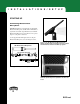
I N S T A L L A T I O N S / S E T U P STARTING UP Connecting Measurement Microphone IMPORTANT: EVOi.net is supplied with a dedicated JBL Measurement Microphone and 100’ XLR - XLR balanced signal cable. Successful setup will ONLY occur if the JBL Measurement Microphone is used. When not in use please keep it in a safe place for future use. Use the supplied 100’ XLR signal cable to hookup the Measurement Microphone, as shown in Figure 5 below.
I N S T A L L A T I O N S / S E T U P STARTING UP INPUT evo SPEAKER STATUS WARNING ANTI FEEDBACK CONTROL FIXED AFC SET FILTERS FREE 1 2 Initial Settings and Powering Up 3 EVOi.net SIGNA AL FIXED SETUP LIVE AFC ON OKAY SPEAKER SYSTEM CONTROLLER Upon activation, all of the LEDs on the A B 1 2 3 4 front panel should light up once and then go out. Depending upon whether or not Figure 8 EVOi.
I N S T A L L A T I O N S / S E T U P STARTING UP (continued) Testing the System At the beginning of or anytime during a system setup, the hookup configuration of the EVO loudspeaker can be tested by using the TEST button. EQ SELECT MUSIC I MUSIC II SPEECH NEUTRAL SETTINGS LOCKED TEST AUTO EQ SETTING EQ SET MAIN OUT SETUP 1&2 HOLD TO CLEAR MAIN This button is used to control the user audio test mode, i.e. pressing it will produce ‘pink noise’ output from each EVO loudspeaker.
I N S T A L L A T I O N S / S E T U P USING THE AUTO EQ SETTING Placing Measurement Microphone for MAIN EVO Loudspeakers For simple applications of up to two EVO loudspeakers hooked up to OUTPUTS 1A and 2B (the MAIN OUT outputs), optimum placement of the Measurement Microphone is illustrated in Figure 10. The placement follows a simple height-to-depth ratio of 1:2. For a given loudspeaker height the optimum position is a distance twice the height away from it, into the listener area.
I N S T A L L A T I O N S / S E T U P Performing Auto EQ for MAIN OUT Loudspeakers SETTINGS LOCKED TEST Before starting, check that the LOCKED indicator is off. If it is on, then use the rear panel switch (Feature 14 page 6) to enable Auto EQ buttons. AUTO EQ SETTING EQ SET MAIN OUT SETUP 1&2 HOLD TO CLEAR MAIN EQ SET AUX OUT SETUP 3&4 AEQ ON HOLD TO CLEAR MAIN Figure 13 - Main Out Setup Button 1. Press the round MAIN OUT SETUP 1&2 button (Figure 13).
I N S T A L L A T I O N S / S E T U P Using More Than Two EVO Loudspeakers If your system consists of more than two EVO loudspeakers then these auxiliary/delay systems should be hooked up to outputs 3A and 4B, the AUX OUT Loudspeakers. LINK IN MONO SUM 4B MONO SUM 3A 2B Once the Measurement Microphone has been positioned and the SETTINGS LOCKED function has been disabled, running the Auto EQ routine is exactly the same as for the MAIN OUT SETUP 1&2.
I N S T A L L A T I O N S / S E T U P DELAY SETTING EVO Loudspeakers hooked up to AUX OUT 3A & 4B outputs can be instructed to automatically set their correct delay and level to perform optimally with EVO Loudspeakers hooked up to MAIN OUT 1A & 2B outputs. A Haas delay will also be added to the AUX OUT Loudspeakers to make sure the MAIN OUT Loudspeakers are the acoustic focus. Before starting, check that the LOCKED indicator is off.
L I V E ANTI FEEDBACK CONTROL SELECTING SYSTEM EQ ANTI FEEDBACK CONTROL EQ SELECT FIXED AFC SET FIXED SETUP HOLD TO CLEAR FIXED FILTERS FREE 1 2 3 LIVE AFC ON MUSIC I MUSIC II SPEECH NEUTRAL O P E R A T I O N SETTINGS LOCKED TEST HOLD TO CLEAR LIVE Figure 21: EQ Select Button The total EVO System can be optimized for an individual program using the EQ SELECT button (Figure 21).
L I V E O P E R A T I O N Live Anti Feedback Control Initiate Live Anti Feedback Control by pressing the square button. LIVE AFC ON will illuminate. As feedback is found, filters will be used to eliminate it.
A P P L I C A T I O N S EVOi.net is the “network” center of any EVO Loudspeaker System. It facilitates access to all EVO Loudspeaker functions and monitoring. EVO Loudspeaker Systems have been optimized for small to mid-size venues, where a pair will sufficiently reinforce sound for an audience of up to five hundred people. They have been designed with specific applications in mind: schools and sports facilities; places of worship; and performance venues.
A P P L I C A T I O N S EVOi.net IN RECTANGULAR ROOMS (continued) Longer Rectangular Room: EVOi.net + 1 Main (Mono) EVOi.324 + 1 Delay (Mono) EVOi.324 In a longer rectangular room, additional coverage may be required. Page 12 of the EVOi.324 Users Guide illustrates a typical application. The diagram below illustrates the hook-up required and typical Measurement Microphone placement, see details page 12 .
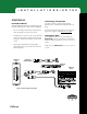
A P P L I C A T I O N S EVOi.net IN RECTANGULAR ROOMS Smaller/Wider Rectangular Room: EVOi.net + 2 Main (Stereo) EVOi.324s The hook up diagram below illustrates the most typical EVO Systems configuration. The inset diagram illustrates the approximate Measurement Microphone position when performing Auto EQ setup (for accurate placement details see ‘Placing Measurement Microphone for MAIN EVO Loudspeakers’ page11). EVOi.net Rear (NOTE: For clarity, power connections are not shown.
A P P L I C A T I O N S EVOi.net IN RECTANGULAR ROOMS (continued) Longer / Wider Rectangular Room: EVOi.net + 2 Main (Stereo) EVOi.324s + 2 Delay (Stereo) EVOi.324s In large rooms, an EVO system as illustrated in the inset diagram may be required. EVOi.324s are hooked up to MAIN OUT 1&2 and the Delays, AUX OUT 3&4. Stereo is required, so EVOi.324s are positioned as shown (refer to EVOi.324 Users Guide page 13) and the Measurement Microphone placement and order of positioning is shown. EVOi.
A P P L I C A T I O N S EVOi.net IN RECTANGULAR ROOMS Longer / Wider Rectangular Room: EVOi.net + 2 Main (Mono Array) EVOi.324s + 2 Delay (Mono Array) EVOi.324s Another typical configuration for larger rooms is to configure two mono arrays, as illustrated in the inset diagram. EVOi.net is hooked up as shown with both MONO SUM switches engaged. EVOi.net Rear (NOTE: For clarity, power connections are not shown.) IMPORTANT: Make sure POWER is off before making connections.
A P P L I C A T I O N S EVOi.net IN FAN-SHAPED ROOMS Small Fan-Shaped Room: EVOi.net + 1 Main (Mono) EVOi.324 EVOi.net hook up configuration and Measurement Microphone are as illustrated below. The setup is identical to EVOi.net in a Small Rectangular Room. EVOi.net Rear (NOTE: For clarity, power connections are not shown.) IMPORTANT: Make sure POWER is off before making connections. Mono Mono In XLR Signal Cable Speaker Placement In Room 1 Mono Approximate measurement microphone placement.
A P P L I C A T I O N S EVOi.net IN FAN-SHAPED ROOMS Medium Fan-Shaped Room: EVOi.net + 2 Main (Mono Array) EVOi.324s For a medium size Fan Shaped Room, broader coverage may be required, therefore the EVOi.324s are configured as illustrated below (see EVOi.324 Users Guide, Applications page15). Hook up for this system is as illustrated below, also approximate position of the Measurement Microphone (see ‘Placing Measurement Microphone for MAIN EVO Loudspeakers’ page11). EVOi.
A P P L I C A T I O N S EVOi.net IN FAN-SHAPED ROOMS (continued) Large Fan-Shaped Room: EVOi.net + 2 Main (Mono Array) EVOi.324s + 2 Delay (Mono) EVOi.324s For a Large Fan Shaped Room, the Main Array is set up and hooked up to EVOi.net as illustrated below. The Delay EVO Loudspeakers are positioned as illustrated and hooked up to AUX OUT 3&4, providing additional coverage towards the back of the listening area.
A P P E N D I X POWER UP OPERATION There are two scenarios: a) EVO Speakers have been changed/replaced or the speakers hook up configuration is different. b) EVOi.net has been changed/replaced. Because of the difficulty in reliably determining which is the appropriate scenario, the same procedure will be used in both situations, and will allow the user to go back to the alternative data set: 1. When powered up, the EVOi.
T R O U B L E S H O O T I N G EVOi.net is used as the interface for the set up and operation of EVO Loudspeakers. The following section may help in resolving some problems that may occur. 1. The front panel is inoperative and does not respond to button pressing: Check the LOCKED indicator. If it is illuminated, then disengage the LOCKOUT Switch on the rear panel (#14 page 6). 2. The CLIP LED’s on the EVOi.net’s INPUT (#1 page 4) are illuminating: The input signal level to EVOi.net is too high.
T R O U B L E S H O O T I N G Error Codes 1st Flash 2nd Flash Digit Digit 2 1 2 2 2 3 2 4 2 5 3 3 1 2 3 3 3 4 3 5 3 6 3 7 4 4 1 2 4 3 4 4 4 5 4 6 Meaning Speaker Over Current. (Short Circuit on amplifier output). Contact Authorized Service Representative. Speaker Over Temperature. (Heatsink temperature too hot). Reduce level to allow speaker to cool. Contact Authorized Service Representative if problem persists. Speaker Under Current. (Open circuit on amplifier output).
T E C H N I C A L D A T A E V O i .net S p e c i f i c a t i o n s Inputs: 2 channels, Max. level +20dB (7.
W A R R A N T Y JBL Limited Warranty The JBL Limited Warranty on professional loudspeaker products (except for enclosures) remains in effect for five years from the date of the first consumer purchase. JBL amplifiers are warranted for three years from the date of original purchase. Enclosures and all other JBL products are warranted for two years from the date of original purchase. Who Is Protected by This Warranty? Your JBL Warranty protects the original owner and all subsequent owners so long as: A.
N O T E S 30 EVOi.
31 EVOi.
EVOi.net 32 EVOi.
S A F E T Y AC Operation Fuse . . . . 6 Power Connector . . . . 6 Anti Feedback Control . . . . 4, 15-16, Clearing Anti Feedback Control . . . . 16 Fixed Anti Feedback Control . . . . 4, 15-16 Live Anti Feedback Control . . . . 4, 15-16 Appendix . . . . 25 Applications . . . . 17-24 Rectangular Rooms . . . . 17-21 Fan Shaped Rooms . . . . 22-24 Audio Connections . . . . 7 Auto EQ Setting . . . . 5, 11-13 Clearing . . . . 12 For MAIN Speakers . . . . 12, 17-24 For AUX Speakers . . . .
A Harman International Company JBL Professional • 8500 Balboa Boulevard • Northridge, CA 91329 www.jblpro.