
Owner's Manual


5
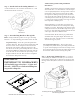
Make sure the gland nut fitting is affixed and tightened in the
proper knock-out location (add a second gland nut to the other
knock-out location if two glands nuts are desired). Slide the
wire through the gland nut (do not tighten the gland nut onto
the wire yet).
Figure 6:
$I¿[LQJJODQGQXWWR7HUPLQDO&RYHU
Plate
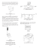
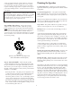
Step 4 – Connect the Wiring to the Ceramic Ter-
minal Block – e Ceramic Terminal Block is attached to
the speaker. Strip the insulation back about 5 mm (about 3/16
inch). Do NOT strip wires back any longer than this. Insert the
bare end of wire fully into the connector (not allowing any bare
wire outside of connector). Only utilize the side of the terminal
where there aren’t already wires connected.
Add a second set of wires in parallel to the same terminals if
a second wire is utilized for looping to another loudspeak-
er. Screw down the hold-down screw until tight using a small
phillips-type screwdriver. Tighten any unused screws to avoid
rattling from vibration.
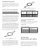
Figure 7:
Connecting Wires to the Ceramic
Terminal Block
(Note that the right-hand wire shown
in diagram is optional. It only needs
to be connected if the chassis of the
driver needs to be connected to a safety
ground.)
Figure 8:
Connecting two sets of wires to the
Ceramic Terminal Block for loop-out to a
subsequent loudspeaker
Figure 9:
Paralleling connections to multiple
speakers for 70V or 100V distributed
speakers systems
Guide to the Pins for Connection -- e Ceramic Terminal
Block contains 3 terminals, as marked on the connector as +
INPUT, - INPUT and GROUND.
Figure 10:
Terminals
Figure 11:
Shown wired (without cover shown)
-