
User's Manual

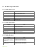
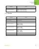
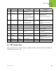


Table Of Contents

Technical Specifications
RF Connectors
General
37www.javad.com
4.3. RF Connectors
J500 is Antenna Input / Output Connector: MMCX RIGHT ANGLE PCB JACK, EMERSON
JOHNSON P/N 135-3701-311.
6 TTLI-1 SLEEP Sleeps/wakes radio
Receive only
TTL Input (3.0v) = Sleep Radio,
(0v) = Wake Radio
7 DPORT-3 MDM_GRN LED control line used
by remotes to indicate
that the remote has
successfully acquired the
signal from base station
to indicate
TTL Output (0v) = Carrier detected
(synchronized)
(3.0v) = No carrier
detected (not synchronized)
8 DPORT-4 RTS Request to Send, gates
the flow of receive
data from the radio to
the user on or off
TTL Input (0v) = Receive data (RxD)
enabled
(3.0v) = Receive data (RxD)
disabled
9 DPORT-2 DSR - TTL Output -
10 RES CONT RESCONT Reset Control TTL Input -
11 TTLO-1 V_CTRL Voltage Control Line TTL Output (0v) = 4.2V DC
(3.0v) = 3.6V DC
12 TTLO-2 MDM_RED LED control line usrd to
indicate
TTL Output (0v) =
Transmission
(3.0v) = No Transmission
13 GND GND Ground - -
14 TTLI-2 ANT_DET Antenna detector input
line
TTL Input (0v) = No Antenna
Detected
(3.0v) = Antenna Detected
15 VCC36 PWR Power Supply External 4.2/3.6 V
16 VCC36 PWR Power Supply External 4.2/3.6 V
PIN # Signal Designator Signal name Deascription I/O Comments