HPT225BT* VHF Modem Operator’s Manual Version 1.2 Last Revised December 17, 2012 All contents in this manual are copyrighted by JAVAD GNSS. All rights reserved.
© JAVAD GNSS Inc., 2012 www.javad.
TABLE OF CONTENTS Preface . . . . . . . . . . . . . . . . . . . . . . . . . . . . . . . . . . . . . . . . . . . . . . . . . . . . . . . . . . . . . . 5 Terms and Conditions. . . . . . . . . . . . . . . . . . . . . . . . . . . . . . . . . . . . . . . . . . . . . . . . . . . . . . . . 5 Regulatory Information . . . . . . . . . . . . . . . . . . . . . . . . . . . . . . . . . . . . . . . . . . . . . . . . . . . . . . 7 Manual Conventions. . . . . . . . . . . . . . . . . . . . . . . . . . . . . . . . . . . . . .
Chapter 3. Command Line Interface. . . . . . . . . . . . . . . . . . . . . . . . . . . . . . . . . . . . . . . 27 1. Command Line Interface Convention . . . . . . . . . . . . . . . . . . . . . . . . . . . . . . . . . . . . . . . . 1.1. Software Switching to Command Mode . . . . . . . . . . . . . . . . . . . . . . . . . . . . . . . . . 1.2. Hardware Switching to Command Mode . . . . . . . . . . . . . . . . . . . . . . . . . . . . . . . . 1.3. Switching to Data Mode . . . . . . . . . . . . . . . . . . . . . .
PREFACE Thank you for purchasing this product. The materials available in this Manual (the “Manual”) have been prepared by JAVAD GNSS, Inc. (“JAVAD GNSS”) for owners of JAVAD GNSS products. It is designed to assist owners with the use of HPT225BT and its use is subject to these terms and conditions (the “Terms and Conditions”). Note: Please read these Terms and Conditions carefully. Terms and Conditions USE – JAVAD GNSS modems are designed to be used by a professional.
Preface Terms and Conditions COSTS. IN ANY EVENT, JAVAD GNSS SHALL HAVE NO LIABILITY FOR DAMAGES OR OTHERWISE TO YOU OR ANY OTHER PERSON OR ENTITY IN EXCESS OF THE PURCHASE PRICE FOR HPT225BT. LICENSE AGREEMENT – Use of any computer programs or software supplied by JAVAD GNSS or downloaded from a JAVAD GNSS website (the “Software”) in connection with HPT225BT constitutes acceptance of these Terms and Conditions in this Manual and an agreement to abide by these Terms and Conditions.
Preface Regulatory Information Regulatory Information There are two modes implemented by firmware for the North America: and . • is preloaded/preprogrammed at the factory for HPT225BT VHF Transceiver sold to US customers. • is preloaded/preprogrammed at the factory for HPT225BT VHF Transceiver sold to customers in Canada. The selection is not available to the customer.
Preface Manual Conventions the take-back and recycling of this product, please contact your supplier where you purchased the product or consult. Manual Conventions This manual uses the following conventions: Example Description FileExit Click the File menu and click Exit Link Space This format represents titles of dialog windows/boxes, names of menu options, identifies program interface objects, such as checkboxes, edit boxes, radio buttons, etc.
Preface Technical Assistance Technical Assistance If you have a problem and cannot find the information you need in the product documentation, contact your local dealer. Alternatively, request technical support using the JAVAD GNSS World Wide Web site at: www.javad.com. www.javad.
Preface Technical Assistance 10 www.javad.
Chapter 1 INTRODUCTION External extra rugged digital high power VHF radio transceiver programmable in frequency ranges from 215 to 255 MHz. The HPT225BT provides half-duplex communication with transmitter output power of 2 W in the frequency band 217 - 220 MHz and 25 W in the frequency band 220 - 222 MHz for USA; 25 W the frequency bands 217 - 218 MHz, and 219 - 220 MHz, 220 - 222 MHz for Canada.
Introduction Getting Acquainted 1. Getting Acquainted The HPT225BT is a rugged and very powerful external radio transceiver 152 mm wide 84 mm deep 72 mm high, weighs 900 g. 1.1. LEDs External LED's (see Figure 2) are used for Link and Line status indication: Positio n LED Name Color Description 1 PWR Green Active if Power connected to modem 2 SYNC Red Active whenever a signal with a level sufficient for reliable reception exists on the radio channel.
Introduction Getting Acquainted 1.3. External Antenna and Bluetooth Antenna Connectors The external antenna connects to the BNC external antenna connector and Bluetooth antenna connects to the SMA connector which are placed on the back panel of HPT225BT. Bluetooth Antenna External Antenna Figure 3. External and Bluetooth Antenna Connectors 1.4. Mounting Bracket The mounting bracket (Figure 4) connects the modem to a standard pole/adapter (Figure 4). Mounting Bracket Figure 4. Mounting Bracket 1.5.
Introduction Getting Acquainted 1.6. Literature HPT225BT literature, including manuals and other product information are available on the JAVAD GNSS website (http://www.javad.com): • HPT225BT Operator’s Manual • Functional specifications 1.7. External Antenna (not included) Antenna type depends on the site requirements, and may be directional or omni-directional. Warning: Do not use HPT225BT without antenna our attenuator to avoid serious damage of your device. 1.8. Storage Precautions 1.
Chapter 2 CONFIGURATION 1. Powering HPT225BT To power HPT225BT use the Battery kit 2 (p/n 99-587100-10). Figure 1. Battery Kit 2 Warning: Powering HPT225BT please observe polarity! 1.1. Power supply requirements A single external power supply is necessary to operate HPT225BT. The external power supply needs to be Listed for US and Certified for EU countries, it needs also to be a Limited Power Source and rated for Outdoor Use and have an output rated for +9... +16V, 10A.
Configuration Antenna Installation To reduce the risk of damage to the equipment, pull by the plug body rather than the output cord when disconnecting the equipment. Do not operate the supply if it has received a sharp blow, been dropped, or otherwise damaged. Do not disassemble the supply. Warning: Before connecting the external power source and the modem, make sure that the power source matches the modem’s voltage and current requirements. 2.
Configuration Connecting HPT225BT and Computer 3. Follow the on-screen installation instructions. Click Next to continue, Back to get back to previous step, or Cancel to quit the installation. 4. Keep the default installation location or select a new location. 5. Click Finish to complete the installation. 6. If desired, create a shortcut on the computer’s desktop for quick access to ModemVU. To uninstall ModemVU use the Start menu on your computer: 1.
Configuration Connecting HPT225BT and Computer computer using special cable (not included in the standard kit) Access Data-Ser Cable, USB/DB15 (1,8m) (p/n 14-578123-01). Figure 3. Cable p/n 14-578123-01 1. Download the zip-archive with USB driver from www.javad.com; 2. Extract the archive to the new empty folder; 3. Connect the USB port of the computer to the USB port of the modem at the switched off power supply by using of a cable. 4. Turn on your computer. 5. Power HPT225BT. 6.
Configuration Configuring HPT225BT 5. Configuring HPT225BT 4. Connect the computer and HPT225BT, as described in “Connecting HPT225BT and Computer” on page 17. 5. Turn on the modem. 6. Start ModemVU. 7. Select the HPT225BT (Figure 4) in the Options window, and click OK: Figure 4. Options window 8. Select the COM port the HPT225BT modem is connected to (Figure 5). Click Connect. Figure 5. Connect to ModemVU www.javad.
Configuration Configuring HPT225BT 5.1. Simplex Protocol When the HPT225BT modem is loaded with special firmware which supports Simplex protocol1, the ModemVU general window will be like below: Figure 6. Radio Link tab. Simplex protocol 1. On the Radio Link tab, set the following parameters (Table 1) and click Apply. Table 1.
Configuration Configuring HPT225BT Parameter Base Modem Repeater Rover Modem Modulation type Specifies a modulation scheme that will be used by your modem. DQPSK is recommended. For both Base and Rover modems the modulation type must be the same. Link Rate The link rate is selected automatically Link Space For both Base and Rover modems the link space must be the same. Forward Error Correction Enable Enable Scrambling Enable Enable 1.
Configuration Checking Firmware Version Parameter Mode Protocol Half-duplex Base or Half-duplex Remote For Base, Repeater, and Removed modems the protocol type must be the same. Frequency Set the frequency in band 215-255 MHz with 6.25 kHz channel spacing. For both Base and Rover modems the frequency must be the same. Output power Select the transmission power for the radio modem. Modulation type Specifies a modulation scheme that will be used by your modem. DQPSK is recommended.
Configuration Loading New Firmware 4. Click FileDisconnect, then FileExit to quit ModemVU. 7. Loading New Firmware The modem uses ModemVU to load firmware onto the modem. For more information, refer to the ModemVU Software Manual, available on the JAVAD GNSS website. 1. Download the new firmware package to your computer. 2. Connect your modem and computer, as described in “Connecting HPT225BT and Computer” on page 17. 3. Start ModemVU.
Configuration Loading New Firmware 6. Open the required firmware folder. Select the .xmd file and click OK (Figure 10): Figure 10. Load New Firmware 7. Wait until the new firmware version process will be complete. 8. Click FileDisconnect, then FileExit to quit ModemVU. 24 www.javad.
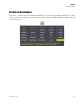
Configuration Bluetooth Configuration 8. Bluetooth Configuration1 Bluetooth module of HPT225BT can be configured in the BT tab (Figure 11). Figure 11. BT tab Use the BT drop down list to switch on/off the module. The PIN code can be inserted in the PIN code field. Click Apply to save settings and apply configurations. 1. Now is supported for Simplex mode only www.javad.
Configuration Bluetooth Configuration 26 www.javad.
Chapter 3 COMMAND LINE INTERFACE The built-in user-friendly Command Line Interface (CLI) allows user to perform a full configuration of the unit and read the statistics and alarm status. It is the most powerful tool to configure the unit. It makes changes to all possible settings that system will not be able to determine automatically. The CLI commands allow user to configure and reconfigure the unit’s settings.
Command Line Interface Command Line Interface Convention 1. Command Line Interface Convention The following convention is implemented in HPT225BT Command Line Interface (CLI): • The Carriage Return/Line Feed (CR/LF, 0x0D/0x0A) is a command delimiter. • The Carriage Return/Line Feed (CR/LF, 0x0D/0x0A) is a reply delimiter followed by the “CLI>” prompt if Echo option is On. • The Carriage Return/Line Feed (CR/LF, 0x0D/0x0A) is a reply delimiter if Echo option is Off (default option).
Command Line Interface Command Line Interface Convention Happy Flow 1. In data-mode the unit starts looking for the Escape-sequence if there is no data from DTE (Data Terminal Equipment) for more than 20 ms (Start Guard Time). 2. If the unit detects the Escape-Sequence: • The transmitter continues sending over the air the data received from DTE before EscapeSequence and buffers the data from DTE; • The Receiver immediately stops forwarding to DTE the data received over the air and buffers it instead. 3.
Command Line Interface Networking Commands 2. Networking Commands 2.1. LINK The LINK command is responsible for configuring radio’s operation mode. It has parameters listed below. Note: In parentheses is shown firmware version, which supports this parameter. If the firmware version is not specified, it means that this parameter is supported in both versions.
Command Line Interface Serial Interfacing Commands Parameter Name Parameter List RTR Base Unit (only for firmware 0 - No Retransmission in the wireless cluster version 1.8) 1- There is Repeater Remote Unit 0 - Auto Detect (Base or Repeater) 1 - Receive from Repeater 2 - Receive from Base Note: The frequency defined by CHAN parameter is not valid if Frequency Hoping mode is selected.
Command Line Interface Serial Interfacing Commands Parameter Name DATARX Parameter List 0 - UART, a default setting 1 - USB 2 - BT The response of command without Parameter Name indicates all values: RATE =0 BITS =8 PARITY =NONE FLOW =NONE DTR =0 RS =RS232 DATATX =UART DATARX =UART, BT 3.2. MPORT The MPORT is an object that responsible for maintenance serial port interface configurations such as data rate and number of bits in a byte.
Command Line Interface Special Commands 4. Special Commands 4.1. BOOT The factory software image and default configuration is set for the new unit. The BOOT command is intended to reboot the unit using specified software image and selected configuration. BOOT IMAGE BOOT CFG The BOOT command with no parameters selects the user settings defined by the prior “parameterized” BOOT commands. 4.2.
Command Line Interface Diagnostics and Identification Commands 4.4. SLEEP The SLEEP command determines the sleep mode parameters. The sleeping AW225BT can be activated by real-time CLK, DTR/RTS lines, and command received through TTL inputs. The user can select one, two, or all three conditions.
Command Line Interface Diagnostics and Identification Commands Software =Ver. 1.8 Rev 04 B24 BootLoader =Ver. 3.0 Rev 03 BT addr =00:18:D7:00:3C:C7 5.2. STATE The STATE command is used to check the state of the wireless link, the unit in the link, and the alarm control lines. To specify a radio unit (local or remote), the CONNECT command must be used in prior of STATE command using.
Command Line Interface Diagnostics and Identification Commands 36 www.javad.
Appendix A SPECIFICATIONS 1. HPT225BT VHF Modem Specifications The following sections provide specifications for the modem and its internal components. 1.1. General Radio Specifications Table 1. General Radio Specifications Parameter Specification Operating Frequency Range1 215-255 MHz (EU) 217-220 MHz and 220-222 MHz (USA) 217-218 MHz, 219-220 MHz and 220-222 MHz (Canada) Channel Spacing1 25/12.5/6.25 kHz (USA, Canada) 25/20/12.5 kHz (EU) Data Rate (25/20/12.5/6.
Specifications HPT225BT VHF Modem Specifications 1. 6.25 kHz channels will occur in increments of 6.25 kHz from 217.00625 MHz to 219.99375 MHz for USA. 6.25 kHz channels will occur in increments of 6.25 kHz from 217.00625 MHz to 217.99375 MHz; from 219.00625 MHz to 219.99375 MHz for Canada. 12.5 kHz channels will occur in increments of 12.5 kHz from 217.0125 MHz to 219.9875 MHz for USA. 12.5 kHz channels will occur in increments of 12.5 kHz from 217.0125 MHz to 217.9875 MHz; from 219.0125 MHz to 219.
Specifications HPT225BT VHF Modem Specifications 1.3. Transmitter Specifications Table 3 lists the transmitter specifications. Table 3. Transmitter Specifications Parameter Specification Output Power EU USA (217 - 220 MHz) USA (220-222MHz) Canada 25 dBm to 40 dBm in 1 dB step (320 mW to 10W) 25 dBm to 33 dB m in 1 dB step (320 mW to 2W) 25 dBm to 44 dB m in 1 dB step (320 mW to 25W) 25 dBm to 44 dB m in 1 dB step (320 mW to 25W) Output Power Control Accuracy ±1.
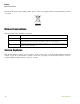
Specifications Compliance 2. Compliance Parameter Specification FCC Part 90 Industry Canada RSS-119 R&TTE ETSI EN 300 113-2; ETSI EN 301 489-5; EN 60950-1:2006 3. Connector Specifications Power Connector Table 5 gives specifications to power connector type 23-500153-01 CONN, HIGH CURRENT PL-700 RECEPT ALDEN 300906. White Marker 1 2 Table 5. Power Connector Specifications Number 40 Signal Name Dir Details 1 Power_INP P 12 volts DC input 2 Power_GND - Ground, power return www.javad.
Specifications Connector Specifications DB15 Connector This provides DB15 connectivity for the HPT225BT with a DB9 for connection to a PC/CE Device for configuration. DB15 (Fem) Figure 1. DB15 Connector This connector provides DB15 connectivity for the HPT225BT with DTE. About using and configuration RS-485 please contact JAVAD GNSS support. Table 6. DB15 Connector Specifications Number www.javad.
Specifications Connector Specifications External Antenna RF Connector The external antenna connector type is a BNC RF connector AEP Connectors p/n 6501-7051-003. External Bluetooth Antenna Connector The external antenna connector type is a SMA connector Linx Technologies, Inc.CONSMA015-R178 42 www.javad.
Appendix B SAFETY WARNINGS Read these instructions. • • • • • • • • • • Keep these instructions. Heed all warnings. Follow all instructions. Clean only with a damp cloth. Do not block any of the ventilation openings. Install in accordance with the manufacturer's instructions. Do not install near any heat sources such as radiators, heat registers, stoves, or other apparatus (including amplifiers) that produce heat.
Safety Warnings General Warnings 44 www.javad.
Appendix C VHF RADIO USAGE Many countries require a license for radio users (such as the United States of America). Be sure you comply with all local laws while operating a VHF radio. Surveying in RTK mode has made VHF the most popular choice for communications between base and rover receivers. Know the strengths and weaknesses of this technology to get the best use out of your receiver. The quality and strength of the VHF signals translates into range for VHF communications.
VHF Radio Usage 46 www.javad.
Appendix D WARRANTY TERMS JAVAD GNSS electronic equipment are guaranteed against defective material and workmanship under normal use and application consistent with this Manual. The equipment is guaranteed for the period indicated, on the warranty card accompanying the product, starting from the date that the product is sold to the original purchaser by JAVAD GNSS’ Authorized Dealers1. During the warranty period, JAVAD GNSS will, at its option, repair or replace this product at no additional charge.
900 Rock Avenue, San Jose, CA 95131 USA Phone: +1(408)770-1770 Fax: +1(408)770-1799 www.javad.com Copyright © JAVAD GNSS, Inc., 2012 All rights reserved. No unauthorized duplication.