Video-PX9000 series / Video-PX498 series/ Video-498PCI series NVIDIA GeForce™ 9000 series User’s Manual Version 6.
Contents INTRODUCTION ......................................................................... 4 FEATURES AND SPECIFICATIONS ......................................... 5 VIDEO- PX9000 SERIES ............................................................ 5 SYSTEM REQUIREMENT .......................................................... 7 CHECK LIST ............................................................................... 7 HARDWARE DESCRIPTION......................................................
TERMS AND CONDITIONS .............................................................. 33 SERVICES AGREEMENT:................................................................ 34 ENTIRE OBLIGATION ..................................................................... 34 REDUCING WARRANTY CLAIM REJECTIONS.....................
Introduction Your PC is now more visual than ever. Supercharge this visual experience with the NVIDIA® GeForce® 9000 series GPU — there is no better investment to provide more vibrant photos, smoother videos, and more realistic gaming. Bring your PC to life Enhance Windows Vista, including the 3D Aero interface and Flip 3D browser.
Features and Specifications Video- PX9000 series NVIDIA® PureVideo® HD Technology1 The combination of high-definition video decode acceleration and post-processing that delivers unprecedented picture clarity, smooth video, accurate color, and precise image scaling for movies and video. Discrete, Programmable Video Processor NVIDIA PureVideo is a discrete programmable processing core in NVIDIA GPUs that provides superb picture quality and ultrasmooth movies with 100% offload of H.
Operating Systems • Built for Microsoft Windows 7, Vista • Windows XP Compatibility • NVIDIA Unified Driver Architecture (UDA) • Fully compliant with OpenGL including OpenGL 2.
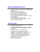
System Requirement • • • • • Intel Pentium® P4 or compatible system with PCIExpress Bus (x16) Extension Slot or PCI slot (depend on card purchased) CD-ROM drive, Quad speed or faster Hard Drive with at least 200MB Free space MS Windows® Vista/XP operating system Minimum 400 Watt power supply (Minimum recommended power supply with +12 Volt current rating of 20 Amp Amps.) Minimum 500 Watt for SLI mode system (Minimum recommended power supply with +12 Volt current rating of 28 Amp Amps.
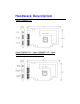
Hardware Description Video-PX9500GT-LX Video-PX9500GT-LE / Video-PX9500GT-DE / VideoPX9400GT-LX / Video-PX9400GT-EX
Video-PX9500GT-DVI / Video-PX9400GT-DVI Video-PX498-Twin 9
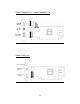
Video-PX498-DT Video-PX498-DLP 10
Video-PX498-LP Video-498PCI-DLP / Video-498PCI-LP 11
Video-498PCI-Twin Product name / PCB version Core Chipset PCB Size Memory Size Video-PX9500GT-LX 82488A NVIDIA GeForce 9500GT W=6.66” X H=4.376” 32M X 32 DDR3 512MB Video-PX9500GT-LE 82498A NVIDIA GeForce 9500GT W=6.66” X H=4.376” 64M X 16 DDR2 1GB Video-PX9500GT-DE 82498A NVIDIA GeForce 9500GT W=6.66” X H=4.376” 32M X 16 DDR2 512MB Video-PX9400GT-LX 82498A NVIDIA GeForce 9400GT W=6.66” X H=4.376” 32M X 16 DDR2 512MB Video-PX9400GT-EX 82498A NVIDIA GeForce 9400GT W=6.
Display Devices Output Video-PX9500GT-LX 1. DVI out - DVI connects to LCD display panel. 2. DVI converts to RGB with DVI-RGB converter for VGA out. 3. DVI out - DVI connects to LCD display panel. 4. DVI converts to RGB with DVI-RGB converter for VGA out. 5. TV-Out – MD-9 pin connector for Component, S-Video or Composite Out.
Video-PX9500GT-LE / Video-PX9500GT-DE / VideoPX9400GT-LX / Video-PX9400GT-EX 1. DVI out - DVI connects to LCD display panel. 2. DVI converts to RGB with DVI-RGB converter for VGA out. 3. VGA out - DVI connects to CRT monitor. 4. TV-Out – MD-9 pin connector for Component, S-Video or Composite Out.
Video-PX9500GT-DVI / Video-PX9400GT-DVI 15
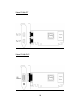
Video-PX498-Twin / Video-498PCI-Twin Converter Cable DIM-9Pin CR Monitor DB 15 VGA DB 15 VGA Connector CR Monitor Video-PX498-DT 16
Video-PX498-DLP / Video-498PCI-DLP Video-PX498-LP 17
Video-498PCI-LP 18
Hardware Installation Installation Procedures !! WARNING!! Discharge static electricity by touching the GROUND such as metal part of your case connected with good power ground before you handle the electronic circuit boards. The manufacturer assumes no liability for any damage, caused directly or indirectly, by improper installation of any components by unauthorized service personnel. If you do not feel comfortable performing the installation, consult with a qualified computer technician. Steps: 1.
Upgrade Steps: Add or change your video adapter to an existing system, you may precede a few steps before you install the new hardware and software (video display driver). The followings are some of the considerations: 1. To add a new adapter, ensure the mainboard has available IRQ for new devices, and there is no conflict between each other. 2. If you try adding this video adapter to an ALL-IN-ONE mainboard (which video port built-in already), then you have to disable that port first – 1) In the .
Software Installation á Windows® 7 and Vista Driver Installation InstallShield® Program: Microsoft Windows® 7 and Vista detects this new hardware and places appropriate display driver from its system folder automatically - it doesn’t matter if you have added a new driver or changed the existing one. To maximize the video board acceleration and increase its performance, you may install the manufacturer’s display driver as follows: 1.
2. Click on “Next” to continue the process. 3. Click on “Yes” to agree to license agreement and continue.
4. Click on “Finish” to complete the installation.
á Windows® XP Driver Installation InstallShield® Program: Microsoft Windows® XP detects this new hardware and places appropriate display driver from its system folder automatically - it doesn’t matter if you have added a new driver or changed the existing one. To maximize the video board acceleration and increase its performance, you may install the manufacturer’s display driver as follows: 1. Autorun feature brings-up the “Welcome Screen”, and you may point to “Display Driver” and then press on it.
1. Click on “Next” to continue the process. 2. Click on “Yes” to agree to license agreement and continue.
3. The Windows system will copy all driver files from source media to your local hard disk; please wait until the process has completed. 4. Click on “Finish” to restart your computer, the new display driver will be in place after Windows boots-up. Notice: We believe that the all the installation steps mentioned above are clear from manufacturer software’s CD to your operating system. Any procedures other than these processes have not been specified.
Technical Assistance Q: Why is the display shifted or changed sizes when I switch display modes? Explain and Suggestion: Some monitors lack auto-sizing features or just do not synchronize properly to the video board output. In some cases, horizontal and vertical display adjustments may be necessary. Use the monitor control panel functions to adjust screen. In other cases, mode type and refresh rate adjustments may be necessary.
Q: Multiple images or unreadable screen after loading video driver. Explain and Suggestion: There are a variety of reasons why the display might be distorted. One common reason is a monitor mis-match. Some older multi-frequency monitors are unable to switch video modes without being turned off, then turned on again. If the problem occurring in windows, make sure that you have loaded that proper video driver, and that the driver is compatible with the monitor being used.
Technical Support In the event you have a technical problem with this product, please read the README files in the software CD_ROM. Updated drivers are available through Jaton Web site. Have following information handy when you contact technical support: ; ; ; ; Name of the product. Software Driver and Version. System Information, such as CPU speed, BIOS version, Monitor Specification, etc. Description of the problems including any error messages. Telephone: (510) 933-8886 (Mon. - Fri.
In Taiwan contact: Jaton Technology Co., Ltd. 10F, NO.194, SEC.3, TA TUNG RD., HIS-CHIH, TAIPEI, TAIWAN R.O.C. Tel : 886-2-8647-1899 Fax : 886-2-8647-2679 In Australia contact: Jaton Technology pty, Ltd. Unit 8, 41-49 Norcal Road, Nunawading, Vic 3131 Australia Tel: (Mel) 03 9873 3999 (Syd) 02 9476 8781 Fax 03 9873 3933 The information in this document is subject to change without notice.
Limited Warranty Manufacturer warrants that the products sold hereunder are free from defects in material and workmanship for a period of two (2) years from manufacturing date. This limited warranty applies only to the original purchaser of Jaton Product and is not transferable. This limited warranty does not apply if failure to Product Registration, or over thirty (30) days from purchase (original invoice date).
hardware components, systems or software they intend to use with. Proof of purchase will be required before any consideration by Manufacturer occurs. TRADEMARK AND COPYRIGHT: This product incorporates copyright protection technology that is protected by U.S. patents and other intellectual property rights. Use of this copyright protection technology must be authorized by Macrovision, and is intended for home and other limited viewing uses only unless otherwise authorized by Macrovision.
persons other than pursuant to written authorization by Manufacturer. Exclusive Obligation This warranty is exclusive. The sole and exclusive obligation of Manufacturer shall repair or replace the defective products in the manner and for the period provided above. Manufacturer shall not have any other obligation with respect to the Products or any part thereof, whether based on contract, tort, and strict liability or otherwise.
charge services such as repair, replacement whether based on its costs. Shipping and installation of the replacement Products or replacement parts shall be at User’s expanse. Services agreement: (1) All applicants shall complete service request form from Manufacturer. (2) All returned checks will be charged a $20.00 fee by Manufacturer. (3) All repair and replacement services allow 4-6 weeks from the date of receiving by Manufacturer.
Reducing Warranty Claim Rejections To reduce the potential of incurring damages not covered by Manufacturers warranties, we strongly recommend the following: • Read your manuals before installing peripherals and/or before making changes to the machine’s configuration; • Ask your dealer if there are any known problems with the system requirements or installation procedures for any add-on products that your are purchasing; • Buy industry standard products where compatibility issue are less likely to surf
Warranty Service Use Only Serial Number - ten or eleven digit code, the serial number consists of the following parts: Packaging Type Manufactured Date Code A 00 8 Production Numerical Code 000015 Year Month XXXXX-XXX-XX xxxx/xxxx S/N: A008000015 00.