
User Guide


Connecting speaker wires.
Loosen speaker terminals by turning counter clockwise. Strip ½”/12 mm in-
sulation off each wire. Twist strands on each wire to form “solid” wire. Insert
one wire into each terminal and tighten terminal by turning clockwise.
Make sure positive (+) is to red terminal and negative (-) to black terminal
for correct phasing.
Adjustment of I/O 3T.
This model is for 70V or 100V line installation. This is mainly used in com-
mercial installations with many speakers and requires an amplifier with
matching transformer outputs. A switch located next to the terminals al-
lows for adjustments of the level of the speaker in 10W, 5W, 2.5W and
1.25W settings. Adjust the switch to the desired level on each speaker.
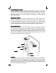
Mounting of speaker.
Remove two covers (j) from the speaker. Place the speaker inside the
curved bracket as shown in fig. 2 and insert thumb screws (k) through each
end of the curved bracket into the speaker. Adjust the speaker to the de-
sired angle and tighten the thumb screws. Re-install the covers. The curved
bracket can be adjusted in the wall bracket by loosening the two ½” allen
bolts and re-tighten them after adjustment.
Painting.
The speaker and bracket can be painted. Spray painting is recommended.
Paint all parts before assembling. Remove the grill from the speaker before
painting and cover the front baffle (l) of the speaker. Apply many thin coats
instead of a few thick coats to avoid the paint running or clogging the grill
holes. Re-install grill after painting.
Fig. 2
j
j
k
k
h
i
i
g
g
l