
Installation Guide


3
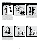
Drill a hole 2 1/4 in. diameter min. - 2 9/16 in. diameter
max. in the floor with an electric drill (1).
Lower the filler assembly over the hole and mark the
locations for the screws with a pencil (2). Then drill
four holes 1/4 in. diameter for the screws in the floor
with an electric drill (1).
Insert the spout (1) into the faucet assembly (2).
Rotate the spout (1) to align correctly with the faucet
assembly (2) then tighten the set screw using hex
wrench (3).
Note 1: Do not reverse the hot and cold supply lines.
Note 2: If installing in concrete the Freestanding Tub
Filler Rough-in Manifold Kit (PT61000) is required.
Note 3: If using PT61000 Rough-in Manifold Kit please
skip to step 5A after the Rough-in Manifold Kit has
been installed.
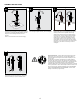
Screw the connectors (1, contained in SKU# PT61000)
into faucet assembly using allen wrench .
Insert supply hoses (1) through cut out hole drilled
into floor / tile.
Tighten the hose (1) into hot and cold water supply (2)
using wrench.
Secure stand pipe (3) using screws (4) and anchors (5).
Do not use anchors (5) if securing into a wood floor.
After installing, cover the floor (6). Continue to step 6.
Loosen the supply hoses (1) using wrench.
Cut a section of floor to run the plumbing as shown in
the diagram.
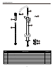
ASSEMBLY INSTRUCTIONS
2
31
1
1
1/4 in. dia.
Floor
1/4 in. dia.
4
5B
2
3
Front
Hot inlet
supply line
Cold inlet
supply line
Min. 280mm
Min. 110mm
210mm~230mm
Min. 280mm
Min. 110mm
Min. 110mm
Floor
3
6
4
5
1
2
5A
1
1
2
Min. 3 in.
(76.2mm)