
Installation & Assembly

www.jacuzzi.com 2 Installation Instructions
Please read and understand this entire manual before attempting to install, assemble or operate this product.
CAUTION
Observe local plumbing and building codes.
These products are designed for installation in or on countertops with a minimum thickness of 1”. The installer
must supply anchors for thinner countertops.
Before attempting to install this product, make sure all parts are present. Compare parts with package and hardware
content lists. If any part is missing or damaged, do not attempt to install, assemble, or operate this product.
Estimated Assembly Time: 60 minutes.
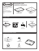
Recommended Tools & Materials
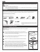
Cut Out Countertop
IMPORTANT: All solid surfaces such as marble and granite must be cut by a qualied
installer or fabricator.
Place the provided template in the desired position on the top surface of
countertop. This position will be determined by the relationship of the sink rim to
the cabinet members and deck mounting ttings.
Cut out countertop by tracing the edge of the female template with a 3/16”
router guide bushing and 1/2” straight cutter bit.
Finish the cut out edge of the countertop with desired nishing techniques.
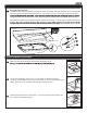
Check cut-out alignment by temporarily placing sink (A1) in the desired
mounting position. Refer to Figure A for general assembly image.
Mount the drain assembly (not included) on the sink, following the faucet
manufacturer’s instructions. Be certain to apply a bead of sealing putty (not
included) on the underside of the drain ange in order to ensure a watertight
seal between the sink (A1) and drain. Remove excess putty after installing the
drain on the sink (A1). Refer to Figure B general assembly image.
Sink
Countertop
SAFETY INFORMATION
Preparation
10'
Putty Knife Adjustable Wrench Plumbers Putty Channel Lock Pliers Silicone Adhesive Tape Measure
Drill & 3/8” Drill Bit Saber Saw Phillips Screwdriver
Note: More specialized tools may be necessary to install
this sink to countertop materials other than wood or wood
composite.
Undermount Installation Instructions
Fig. A
Fig. B
1
2
3
4
5