
Installation Sheet
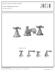


j a c l o i n d u s t r i e s | 129 Dermody Street Cranford, NJ 07016
p 908.653.4433 | 800.852.3906 f 908.653.1717 | 800.852.4133
REVISED 9.1.2016
JACLO.COM
|
PG 3
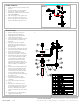
FIGURE 5
HOT
COLD
Spout Installation
Note: Some items have been
pre-assembled at the factory to
ensure quality and t. Some
disassembly may be required
during installation.
1. Remove nut (12), washer (11), and “T”
if installed from spout mounting nipple
(13). Figure 1.
2. Slide the spout assembly through the
counter top or basin.
3. Slide washer (11) onto spout nipple.
Pop-up rod cut out on washer faces
rear of spout. Install nut (12) onto
spout nipple and secure spout to
counter top or basin once positioned
correctly. Figure 2.
4. Install “T” (14) onto nipple (13) using a
NSF listed joint compound.
Valve Installation
1. Identify hot and cold valves. Hot
has red dot and cold has blue dot.
2. Install hot valve on left side of spout
when facing sink. Figure 3
3. Install cold valve on right side of
spout when facing sink. Figure 3.
4. Remove handle, escutcheon, and
top valve nut.
5. Adjust lower valve nut (8) down
away from valve stem. Figure 4.
6. Install valve through bottom of
counter or basin. Figure 4. Install
nut (8) on to valve and tighten.
7. Find “A” dimension Figure 5 & set
escutcheon to specied height.
8. Install top nut and escutcheon on to
valve and tighten.
9. Adjust if necessary.
Hose Installation
1. Connect hot hose to hot valve outlet
and "T". Figure 3.
2. Connect cold hose to cold valve
outlet and "T". Figure 3.
3. Connect supply hoses or tubes
(not supplied) to base of hot and
cold valves. Figure 4.
FIGURE 1
FIGURE 3
FIGURE 4
FIGURE 2
Valve Stem
Counter or
Basin
1¼”-1½”Ø
Counter or
Basin
1¼”-1⅜”Ø