JA SOLAR JA SOLAR PV MODULES INSTALLATION MANUAL Regular Single glass Modules Bulling No 8, Nuo District, Belling, C! Tel: Fax: +86 (10) 83611999 Etna Road, Fantail Varanasi no.
1 INTRODUCTION etn ey Te Ey This ‘installation Manual contains essential information for electrical and mechanical installation that you must know before handling, installing JA Solar Modules. This Manual also contain safely information you need to be familiar with.
Product ide 1. Name ate. describes the product type) Peak power, Max. power current, Max. power cottages, open cull voltage, short culture currant, a as measured under standard test conditions; Clarifications mark the maximum system voltage sic. 2 Current Sorting: Modules ars sorted out according fo their Max power current, referred as a corresponding symbol’ "Current class XK attached, In which x takes the value marks physically the highest current).
Ark ably under dry conditions, and use only dry os. Do rot hands Modes when that ars wet unities wearing appropriate protective equipment.
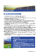
Installation position and working environment JA Solar Modules are Intended for uss In terrestrial applications only no outer space uss, {30 not use mirrors of other magnifiers fo concentrate sunlight ante the modules Modules must be mounted on appropriate mounting brochures positioned on suitable buildings, the ground, or other brochures suitable {for modules (e.g. carports, bulling facades or FY trackers) Modules must not be installed in locations where that could be submerged in water.
&. Mechanical Installation magi ee eg Ensure the installation method and supporting system of Modules is strong sough to withstand all the load conditions. The Installer must provide this guaranties. The installation supporting system must be tested by the third parody organization with the analysis ability of Static Chimerical, coordinator Io the eal rational or international standards.
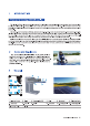
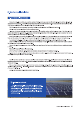
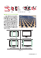
Modules should be bolted fo support structures through mounting holes located in the Fatima's back flanges. Refer to what la shown In Figure 2 (Mounting Natalia) SOLAR MODULE For your reference, please use the components spoiled below: WAR A foi 2.
rks Submariner re Liar A Figure 3 Clamp Devitalize (Unbecoming) Camp 8 The marginalia level of lad condition is applicable io the installation in most of environmental conditions: the maximum static load on the back of the modules is 2400 Pall. wind load), and the maximum silica load on the front of modules is 2400 Pa (Le. wind and snow load).
Cables and Wiring These junction boxes have been designed to be easily interconnected in series for their well-connected cable and the connector with PET (IPECAC) protection grade. Each Mods hiss two single-conductor wires, one positive and one negative, which are per-wired inside the junction box.
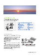
7. Grounding JA Solar Modules uss an anodize oxidized aluminum rams (0 resist corrosion. So the ams of Modules should be connects to the equipment grounding conductor to prevent thunder and satirical shock, The grounding devices should fully contact with the Inside of the aluminum alloy, and pens irate ihe surface of the frame oxidation film. Pleads don't drill any additional grounding hole on the frame of the Modules, otherwise JA Solar express'y disc'aim liability for voiding the warranty.
Grounding by using unused mounting hole The existing mounting holes which have not bean suds can be used for grounding A Direct the grounding clamp to the mounting ho'es In the frame. Thread the grounding clamp and the fame with grounding bolt. B. Put the toothed skeletal into the other side, then tighten and look the nul. The recommended torque of locking the nut 1s 2.0 Ne-2.2 N-M ©. Thread the grounding clamp with grounding wire.