
Installation Guide Instruction Manual

INSTALLING THE SLIM LINE® INSTRUMENT SERIES PAGE 6 OF 14
REV B
- BATT +
Master switch
Starter Starter solenoid
Master switch
contactor
Bus
F G
B
external shunt
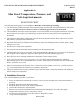
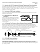
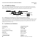
Ammeter Configuration
Alternator
+
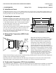
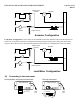
Load Meter Configuration. Or the shunt can be installed between the alternator output and the main bus in
which case it will be the load meter configuration showing alternator load (positive only). Be sure that the
negative side of the shunt is connected to the main bus in the load meter configuration. There is no alarm.
- BATT +
Master switch
Starter Starter solenoid
Master switch
contactor
Bus
F G
B
external shunt
Load Meter Configuration
Alternator
+
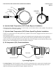
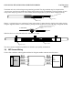
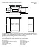
16) Connecting to the instrument
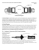
All temperature and pressure instruments Volt-Amp instrument
rear of instrument
connector
hook down
red
black
gray
rear of instrument
red
black
gray
V-A switch
white + shunt
gray - shunt