Pilot’s Guide Engine Data Management EDM-960 Primary Copyright 2009-2011 J.P. Instruments, Inc. All Rights Reserved J.P. INSTRUMENTS INC. Information: P. O. Box 7033 Huntington Beach, CA 92646 Factory: 3185 B Airway Ave. Costa Mesa, CA 92626 (714) 557-5434 Fax (714) 557-9840 www.jpinstruments.com www.JPITech.com www.buyJPI.
Table of Contents Section 1 Getting Started Fuel Flow Computer Basics Control Button Basics Display Screen Basics Remote Auxiliary Display Basics RPM and MAP Display Basics Linear Bar Graphs Display Basics LeanFind Basics Section 2 Interpreting Data Operation for each Phase of Flight Typical Normal Measurements Engine Diagnosis Chart Section 3 Displays and Controls Control Buttons RPM and MAP Displays Scanner Displays Remote Auxiliary Display Hobbs Display Dimming the Display Section 4 Operating Modes Manua
Setting the GPS Com Format Section 10 - Custom Key Card Section 11 - Setting Fuel Calibration Points Collecting Fuel Level Calibration Data Entering / Editing Fuel Level Calibration Data Troubleshooting the EDM-960 Diagnostic Testing on Startup and During Flight Diagnostic Messages Section 12 - Appendices Shock Cooling Navigation Data Formats Navigation Data Ports for GPS Comm Interface connections to selected GPS models Section 13 - Technical Support 45 45 46 52 52 53 55 55 56 56 56 57
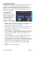
EDM-960 SYSTEM DISPLAYS EDM-960 Main display Remote Auxiliary Display (RAD) Twin Center line thrust Configuration
Product Features • • • • • • • • • • • • • • • • • • • • • • • • • • • • Hands-free, automatic scanning LeanFind finds the first and last cylinder to peak with true peak detect—eliminates false peaks Displays both leaned temperature below peak and peak Voltage monitoring with alarm (see AFMS) Amperes (load or charge/discharge meter) Programmable alarm limits Exhaust Gas Temperatures (EGTs) to stable 1°F resolution DIF low to high EGT with alarm Shock cooling monitored on every cylinder Fast response prob
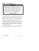
Section 1 - Getting Started Important Note! You must have the remote auxiliary display—RAD— installed on the instrument panel of your aircraft. This is required for FAA certification of the EDM-960 as a primary instrument. Upon start up, the RAD displays the make and model of you aircraft, which must be verified before you can rely on the EDM-960 for use as the primary engine instrument cluster.
Fuel Flow Computer Basics The fuel flow computer tracks the fuel flowing to the engine and computes various values based on this. At installation, then each time you refuel the aircraft, you must inform the EDM about how much useable fuel is onboard. This is done via the REFUEL function. There are three ‘Quickset’ ways to do this: 1. Main 74.0 GAL: MAIN tanks are filled (no other fuel onboard). 2. Main + Aux 94.0 GAL: MAIN +AUX tanks are filled. 3. Adjust? 0.0 GAL: Partial fuel added to existing quantity.
Remote Auxiliary Display Basics The Remote Alarm Display ‘RAD’ provides alarm display, RPM and MAP, and is located directly in front of the pilot. Upon power up, the RAD shows the Aircraft model, engine type and declares instrument status: ‘Primary’ (if applicable). Before each flight, confirm that it matches your aircraft requirements.
Scanner® Display Basics The EDM Scanner section is located in the lower left area of the screen. It consists of a graphical display of EGT and CHT (and TIT if so equipped) and a digital display that automatically scans the various parameters. You can select Manual Mode by tapping STEP to lock onto the parameter of interest. To return to Automatic scan mode, tap LF followed by tapping STEP. LeanFind Basics Simply pre-lean, tap the LF button (Lean Find) and begin leaning.
Section 2 - Interpreting Data Operation for each Phase of Flight (worth adding to your run-up checklist.) Suggested setup: • Set engine to run-up RPM Engine Run-Up Normalize view • Manual mode Verify: • • uniform rise of about 50°F in all EGTs in single magneto operation. uniform rise of EGTs with application of the mixture control.
Suggested setup: Take-Off, Climb, and Full Throttle Operations • • Standard view Automatic mode Verify: • EGTs and CHTs consistent with past climbs. EGTs should be in the 1100 to 1300°F range (100° to 300°F cooler than cruise) due to fuel cooling. Be alert for: • high EGT in one cylinder, 300°F above the others may indicate plugged injector or leaking manifold gasket on a carbureted engine. At high density altitude an overly rich mixture can significantly reduce engine power.
Typical Normal Measurements The following chart lists typical normal measurement values that you will observe for most general aircraft engines. Your particular engine’s ranges may not fall within these values.
Engine Diagnosis Chart The following chart will help you diagnose engine problems in your aircraft (note: only one engine is shown). Display Symptom Probable Cause Recommended Action TIT ~100° higher This is normal than EGTs 75° to 100° EGT rise for one cylinder during flight Spark plug not firing due to fouling, faulty plug, wire or distributor. Enrich mixture to return EGT to normal. Have plugs checked.
Continued: Display Symptom Probable Cause Recommended Action Decrease in EGT Intake valve not for one cylinder opening fully; faulty valve lifter. Have valve lifter or rocker arm checked. Increase in DIF at low RPM Low compression (blow by) in cylinder Check compression. EGT and CHT not uniform Check injectors and Normal for carbureted engines. plugs. Dirty fuel injectors or fouled plugs. Decrease in EGT Decreased induction Check for change in manifold pressure. for all cylinders airflow.
Continued: Display Symptom Rapid rise in CHT of one cylinder Probable Cause Detonation. -> Sudden off scale Pre-ignition rise for any or all cylinders Normalize view - > or failed probes - > Recommended Action Reduce power. Full rich & reduce power. Change to Standard view Check probes (no picture) Loss of peak EGT Poor ignition or vapor Have magneto tested. in fuel injection system. (no picture) Decrease in peak or flat EGT response to leaning process Detonation.
Section 3 - Displays and Controls The EDM monitors engine temperatures, pressures and voltages, assists in adjusting the fuel/air mixture, and helps diagnose engine malfunctions. There are multiple components of the user interface: • • • • • Four front panel operating buttons below the bottom of the display.
2nd Button • In Automatic or Manual modes, tapping the LF button will activate the LeanFind mode. • In the LF mode holding the LF button after peak EGT is found will display the peak EGT. • In Automatic or Manual modes holding the LF button for three seconds will toggle between Standard and Normalize (NRM) views. • In the programming mode, tapping the PLUS or MINUS button will allow you to edit a parameter value.
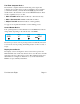
RPM and MAP Displays The upper left side of the display shows RPM above the MAP. The arcs represent the analog values. Percent horsepower is shown below the MAP readouts. Scanner Displays Digital CHT EGT (blue) Cylinders 1 thru 6 T is TIT White square is Cylinder I.D. Box CHT (white) LEFT ENGINE TIT (Lt. blue) RIGHT ENGINE Scanner EGT and CHT Analog Bar Graph The height of each column represents a EGT or CHT or TIT (if installed) temperature.
Normalize / Standard View To toggle between Standard and the Normalize views, hold the LF button for three seconds until the NRM icon toggles on or off. Note: Normalize cannot be activated while in Lean Find mode. • Standard view (when the NRM icon is not lighted): the EGT represent absolute temperature. The top of the columns indicate absolute temperature relative to the adjacent range mark temperature scale.
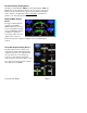
Linear Gauge Display Section The linear bar graphs are arranged in a three by three matrix on the right half of the display. A typical layout is depicted here (Note: your actual configuration may vary).
Remote Auxiliary Display See the important note on page 1 regarding the RAD. The remote auxiliary display ‘RAD’ provides redundancy and allows positioning a smaller display directly in front of the pilot. Upon power up the RAD displays the EDM’s programmed configuration (aircraft make and model and primary status). Confirm that it matches your aircraft configuration before using the instrument.
Section 4 - Operating Modes The EDM has four basic operating modes: Automatic, Manual, Program and LeanFind. LeanFind is described in the next section; Program mode is described on page 37, ‘First Time Setup and Customization’. When you first turn on the power the EDM starts in the Manual mode, but will enter the Automatic mode after a few minutes. The Automatic mode provides you with engine monitoring information for the majority of flight conditions. To optimize the mixture, use the LeanFind mode.
Manual Mode To activate Manual Mode, just tap the STEP button. Use Manual mode to lock on one measurement, such as your hottest CHT. Select desired parameter by tapping STEP button. Return to Automatic mode by tapping LF and then tap STEP. Disable Automatic mode by setting ‘Auto Scan Rate 0’. See Pilot Programming.
Fuel Used Ground Speed Charge Amps GAL 38.4 USED 38.5 AIRCRAFT GS 140 KTS Load 12 AMPS 10 Since last refueling or trip total. Ground speed from GPS (Present with GPS interface) Section 5 - LeanFind The EDM supports two methods of leaning; ROP (Rich Of Peak) and LOP (Lean Of Peak). Note: on power-up, the unit defaults to Rich Of Peak mode, but is easily changed to Lean Of Peak mode.
Best power range First cylinder to peak. Use Rich of Peak leaning Best economy range Last cylinder to peak.
Rich of Peak leaning is as simple as: A. B. C. D. R Pre-lean your mixture. Tap the LF button (verify ROP appears). Lean mixture until LEANEST flashes (peak found). Enrichen to the desired value ‘Rich Of Peak’. Procedure Scanner Example (one engine) Comments 1 Establish cruise at 65 to 75% power. to 50°F estimated rich of peak on any EGT: _________°F. 1490 370 EGT CHT 3 Wait one minute 4 Tap the LF button ROP 5 Lean the mixture at EGT approx. 10°/second without pausing.
Lean of Peak leaning is as simple as: A. Pre-lean your mixture. B. Tap the LF button (verify LOP appears). C. Lean mixture until RICHEST flashes (peak found). D. Enrichen to the desired value ‘Lean Of Peak’. L Procedure Scanner Example Comments (one engine) 1 Establish cruise 6 7 approx. 10°/second without pausing. (cylinder I.D. box flashes when a EGT rises 15°F) After the first EGT peaks, you will see LEANEST for one second and bars coming from the top down. Continue leaning.
LeanFind Procedure—General Explanation Lycoming and Continental have established specific restrictions on leaning that must be followed, such as percent power, climb leaning, and TIT limits. Lycoming recommends operation at peak EGT at 75% or less power only. Continental recommends operation at peak EGT at 65% or less power only. This guide does not supersede specific recommendations of the engine or airframe manufacturer. It is your responsibility to know your aircraft’s limitations.
Lean Find - Rich Of Peak Detection: Eventually, one cylinder will reach peak before any of the other cylinders. The EDM will determine this automatically. The EDM will indicate success in finding a peak by displaying the word LEANEST for two seconds and flashing the peaked EGT column. The Scanner® Information Area will also display the current value for the peaked EGT and fuel flow value, for final adjustment of the mixture.
Lean Find - Lean Of Peak Detection: Note: This mode should only be used when your engine is equipped with balanced fuel injectors. When using the Lean of Peak mode, you lean until all EGT’s decrease slightly below their respective peaks. The EDM has automatic peak detection and will sequentially indicate leaning progress. When the first EGT peaks, the word LEANEST appears and the cylinder I.D. box highlights the cylinder number. Each column successively drops as leaning continues.
The following illustrations show typical displays when the first EGT peaks and then the last EGT peaks. You finalize mixture on the ‘last to peak’ (right engine being leaned only). ‘First to Peak’ detected - Lean of Peak mode Column appears for ‘first to peak’ (leanest) Cylinder I.D. box flashes, until another EGT peaks. Difference from where EGT peaked Current Fuel Flow ‘Last to peak’ detected - Lean of Peak mode Column of ‘Last to peak’ (richest) EGT momentarily flashes Cylinder I.D.
Expanded Leaning Procedures Lean Of Peak mode: During the ‘lean of peak’ process, the EDM hunts for the last cylinder to peak. This is because, ultimately, you want to have ALL cylinders operating on the lean side of peak. You will final adjust your mixture to this cylinder. To provide a unique graphical depiction during lean of peak operation, the columns become inverted after the first EGT goes just below peak. Each EGT column then originates from the top of the display and drops downward.
Section 6 - Fuel Flow Operation Fuel Management Without a means of measuring accurate fuel flow, you must rely on the aircraft fuel gauges or total time of flight. Aircraft fuel gauges are notoriously inaccurate (they are only required by the FAA to read accurately when displaying empty). Determining fuel consumption by multiplying time of flight by estimated flow rate is, at best, an approximation, and assumes a constant fuel flow rate for each phase of flight.
Start Up Fuel On power-up, you will be prompted to enter any fuel you might have added to the aircraft (this process updates the REM and USD values). The EDM will flash REFUEL? . If you didn’t add any fuel, simply tap EXIT to quit, otherwise tap NEXT to pick one of the three quickset choices below: Choice 1) MAIN 66.0 GAL : Tap SAVE to accept or NEXT for choice #2. This shortcut sets REM to the MAIN tank value (66 in this case) you set up in your fuel computer. Choice 2) MAIN + AUX 82.
Example A: Aircraft has two fuel tanks with internal tabs. Your tank capacities are: to the tabs = 66 usable to the caps = 66+16= 82 usable When you refuel: ‘MAIN 66.0’: use this shortcut when filling to the internal tank tabs. ‘MAIN+AUX 82.0’: use this shortcut when filling to the caps. (only one tank is shown in each of the two scenarios) ‘MAIN+AUX 82.0’ tab tab ‘MAIN 66.
Example B: Aircraft has two MAIN and two AUX tanks. Your tank capacities are: ‘MAIN = 60’ (30+30 usable) ‘AUX = 14’ (7+7 usable) When you refuel: ‘MAIN 60.0’: use this shortcut when filling only MAIN tanks, (! AUX tanks must be empty). ‘MAIN+AUX 74.0’: use this shortcut when filling MAIN and AUX tanks. (only one wing shown in each of the two scenarios) ‘MAIN 60.0’ Main Tank Aux Tank ‘MAIN+AUX 74.
Example C: Aircraft has two MAIN tanks. When you partially refuel, use: ‘ADJUST? +0.0’: use this to add the amount of fuel you pumped into the aircraft (it doesn’t matter which tanks you added to - the EDM totalizes ALL onboard usable fuel). In this example you will add ‘+14.0 GAL’, the same as your fuel slip reads. This will be added to the totalizers REM value. ‘ADJUST +14.
Resetting ‘ USED’ USED is automatically reset whenever you perform REFUEL on your EDM (except if TRIP mode = yes). After filling your tanks and prior to engine start you should inform the EDM that the aircraft has been filled. In this case USED is automatically set to zero. If you forgot and have already started the engine, and then you inform the EDM that tanks have been filled, then some fuel has already been used.
Section 7 - Alarms Whenever a measured parameter falls outside of the normal allowed operating limits, i.e. goes beyond redline, the main display will blink an ALERT icon in red paired with that parameters current digital value and a flashing red label (i.e. CHT) will appear in the Scanner area and the RAD. For example, if CHT 2 is at 480, and redline is 460, it would be displayed as 480 CHT (CHT flashes in red). Other alarm examples are: 2780 RPM, 15 O-P, 34 F-P, 240 O-T.
Section 8 - Memory and Data Download The EDM compresses and records all displayed parameters once every six seconds (default) in Long Term Data Memory (note: you can change this rate to be 2 to 500 seconds). This data is retrievable by inserting a USB Drive into the jack on the front of the instrument and following the prompts. You can choose to retrieve ‘ALL’ the data stored in the EDM, or only the ‘NEW’ data recorded since your last retrieval. In either case, the selected data in the EDM is not erased.
e. When the download is complete the display on the EDM will show DONE and then return to normal operation. f. Wait until the process is complete then remove the USB flash drive from the USB connector. Transferring data from the USB Flash Drive to a PC To transfer your data from the USB flash drive to your PC, follow these easy steps. 1. On your PC, start the EzTrends program. 2. Plug in the USB flash drive into an available USB port. 3. In EzTrends, select the Move and Plot Data from Memory Stick option.
Section 9 - First Time Setup and Customization Your EDM comes with most settings programmed. However some settings you will fine tune to your installation and/or preferences. We recommend you perform the following minimum set up: 1. Pilot Programming Mode: • Set the GPS Communications format to match your type of GPS. • Fine tuning of fuel flow K-factor is important as it affects your fuel computer parameter accuracies. • Set the Engine HP equal to your engines rated horsepower.
Pilot Programming Mode To start Pilot Program Mode, hold both STEP and LF buttons until you see PROGRAM for two seconds. Then tap the NEXT button to advance to the desired item in the list. Hold the NEXT button to back up in the list. Either tap NEXT until you see END? Yes and then tap EXIT or hold both NEXT and LF to save changes. First button advances to NEXT item Second button selects values Program Mode Refuel Stays on for two seconds. Tap Refuel to change fuel status. Exits program mode when done.
HP Constant= 125 10 ⇔999 Engine Constant = 14.9 1 ⇔ 99.9 Engine HP = 225 10⇔999 Lft MAP -3.0⇔+3.0 Rft MAP Lft K-Factor 1= 29.90 Rht K-Factor 1= 29.90 00.10 ⇔ 99.99 GPS Format = 6 0⇔8 Time: 18:23:59 00:00:00 ⇔ 23:59:59 For Your Safe Flight Hold NEXT and button 2 until you see ADJUST. Tap PLUS or MINUS to adjust (%HP display will reflect changes). Hold NEXT and button 2 to save changes. Hold NEXT and button until you see ADJUST. Tap PLUS or MINUS to adjust.
Date: 05/14/09 01/01/00 ⇔ 12/31/99 Hold NEXT and button 2 for 5 seconds until you see ADJUST. Use Month, Day, Year to adjust. Tap SAVE to save changes. Tap NEXT to skip to next item. END? Yes END? Yes Yes exits the pilot program mode. No reenters pilot program mode. Adjusting the HP Constant for Rich of Peak Operation To fine tune the %HP readout, follow this procedure airborne between 5,000 and 8,000 feet MSL. 1.
3. Adjust the value using the PLUS or MINUS until the value equals the altimeter setting (sea level airport). The adjustment range for the MAP is ±3.0 inHg. 4. Hold both NEXT and Button 2 until you see SET. 5. Repeat for right engine. Adjusting the HP Value You must set the nominal horsepower of your engine. This value is used to calculate the percent horsepower display. 1. Enter the pilot program mode by simultaneously holding the STEP and LF buttons for five seconds. 2.
Fine Tuning the K factor Aircraft installation will affect K factor. Because of this you should ‘finetune’ the K-factor, for your aircraft, as described below: 1. Fill each aircraft tank that each engine will run from (note: engine return lines must return the fuel to each respective tank). ‘Refuel’ EDM, noting that ‘USED’ resets to zero for each engine. 2. Fly aircraft for 2 to 3 hours. Immediately after engine shutdown, record EDM ‘USED’ parameter for each engine in chart below. 3.
Every time you fine tune the K factor, change it by only half of the amount calculated above, and record the measurements here: Date Engine EDM actual Curren fuel used fuel used t K factor New K factor = x/ Pilot’s initials IMPORTANT: after adjusting K factors you must apply a correction factor to the EDM indicated fuel USED and indicated fuel REMaining, accordingly. We recommend you top the tanks and ‘Refuel’ the EDM to eliminate this requirement. Entering the K factor 1.
Programming Trip Mode Trip Mode keeps a running total of fuel used (USD) for all flights. If Trip Mode = No, fuel ‘USD’ is zeroed after updating the EDM’s fuel computer via Refuel modes. NOTE: to clear the fuel used display at any time, tap STEP until you see USD. Hold both DIM and ALL/EGT/FF buttons until the display shows ‘.0 USD’. 1. Enter the pilot program mode by simultaneously holding the STEP and LF buttons for five seconds. 2. Tap NEXT repeatedly until you see TRIP Used? No . 3.
Setting the GPS Com Format This process allows you to select what GPS communication format the EDM should use when sending fuel flow data to the GPS. See table below with the numeric GPS-C values and their corresponding formats. 1. Enter the pilot program mode by simultaneously holding the STEP and LF buttons for five seconds. 2. Tap NEXT repeatedly until you see GPS FORMAT . 3. Hold DIGIT and Button 2 until ADJUST appears 4. Select desired code value using PLUS or MINUS. 5.
Section 11 - Setting Fuel Calibration Points The EDM interfaces to various fuel level sensor types to facilitate direct reading of the fuel level in the aircraft fuel tanks. The EDM has a multipoint fuel calibration table that you must enter. This table contains calibration values (stored in non-volatile memory) used to translate sensor readings into the displayed fuel quantity values. The calibration information is collected and recorded on paper for later entry into the EDM.
Capturing the sender reading at each calibration point: Getting Started…Collecting Fuel Level Calibration Data using the EDM as a meter. 1. With power off, hold in Button 4 (Button 1 being far left) and then turn on power. For each EDM monitored tank, create a paper table with the desired number of calibration points (2 to 5) and at what volume each will be. Number of calibration points to be entered into the system later. The zero gallon point reading is always taken with unusable fuel in the tank.
After you have collected your data After you have collected your data…Entering / Editing Fuel Level Calibration Data The Fuel Table Editor is a spreadsheet type format allowing you to easily see the volume and related calibration values side by side. You can easily navigate through the cells to enter values. 1. With power off, hold in Button 3 (Button 1 being far left) and then turn on power. Wait until you see ‘Do you agree with the disclaimer?’. Tap YES if you agree and wish to continue. 2.
3. Tap USER when you see ‘Do you want to restore user table?’ (Note: tapping FACTORY causes the fuel table stored on the Key Card to over-write any previous user entries in the fuel table. Use FACTORY if you want to start from the original factory default). 4. Tap POINTS when you see ‘Do you want to edit the table?’.
5. You see ‘Points in LEFT’, the current calibration points for the LEFT tank. 6. Tap/hold VALUE to change to the desired number of calibration points for this tank (2 to 5). Each Tank can have a different set of calibration points. So 5 points for Main and 2 points for Aux. 7. Tap TANK to select the next active tank and repeat previous step. Continue until all tanks ‘points’ have been set. 8. Tap TABLE. You see ‘Fuel Table Data’ ( White at top of screen) with a table.
9. Tap/hold STEP to select the cell you want to edit. Tap EDIT to change the value. Tap SAVE to record it. Follow the on-screen menus to edit the value. Keep tapping DIGIT to move it across. 10. Repeat previous step until all tanks data have been entered. 11. You see ‘Save fuel tank data?’. Answer SAVE to store all final data values or CANCEL to return to table editing.
Troubleshooting the EDM-960 Common Misapplications Problem Display freezes or may be incorrect LeanFind finds a “peak” too soon Peak not found during LeanFind Off-scale EGT columns, too high or low First cylinder to peak is not the hottest EGTs rise during single magneto check EGTs not uniform during low power operation Situation A power transient could cause the processors to malfunction Failure to pre-lean before performing LeanFind or stopping while leaning Leaning too slowly Lean Find not activated
Diagnostic Messages The following displays indicate a malfunction in the system: Startup and Operational Diagnostics 0.0 GPH --- GPH --- H.M OPEN PRB BAD-PRB Zero’s indicate Fuel flow is too low to register Dashes indicate No fuel flow transducer signals Dashes indicate No fuel flow transducer signals Open probe. Wiring to probe is open circuit. Check wiring and crimps. Swap probes to troubleshoot. Bad probe. Erratic reading. May be poor electrical connection. Swap probes to troubleshoot.
GPS Interface Diagnostics Measurements ‘xxx REQ’, ‘xxx RES’ and ‘xxx MPG’ are all missing from the scan. No communications from GPS receiver to EDM. Possibly no connection or aircraft GPS is off. NO - COM message and ‘xxx REQ’, ‘xxx RES’ and ‘xxx MPG’ are all missing from Communications are received by EDM and the Auto-Protocol setup is in process. Verify correct output format setup in GPS receiver; check GPS connections. the scan.
Section 12 - Appendices Shock Cooling Cooling the cylinders too fast can result in cracking and eventual failure. Lycoming Service Instruction 1094D (March 25, 1994) on Fuel Mixture Leaning Procedures states: “At all times, caution must be taken not to shock cool the cylinders. The maximum recommended temperature change should not exceed 50°F per minute.” JPI checks shock cooling on all cylinders and displays the rate of the cylinder that is shock cooling the most.
Navigation Data Formats Output of GPS; input to EDM. The EDM automatically configures itself for one of three industry standard data formats: Format Baud NMEA-183 (Marine Nav Data Format) 4,800 This is the format for most handheld GPS receivers. Loran must have sentences RMA & RMB. GPS must have sentences RMB & RMC. Aviation Data Format 9,600 “Output sentence type 1” Required sentences are: A, B, C, D, E, I and L first character identifier byte.
Section 13 - Technical Support JPI offers web, e-mail and telephone technical support. Have your model and serial number ready when you call. Call JPI for a return authorization number before returning any equipment. J.P.INSTRUMENTS Inc. 3185 B Airway Costa Mesa, CA 92626 Call: (800) 345-4574 Web: www.jpinstruments.com or www.JPITech.com Limited Warranty J.P. Instruments Inc. (JPI) warrants all parts in your new EDM-960 to be free from defects in material and workmanship under normal use.
Index * * Pre-leaning procedure:, 23 A Accumulate, 44 total, 33 Alarm priority, 34 Alarm limits, 34 display, 12 Alarms, 34 Alerts, 34 Allied Signal, 45 Automatic mode, 17 Aviation data format, 53 B Bar graph, 3, 15 column resolution, 13 Baud rate, 53 Blinking display, 21, 22, 27 Button DIM, 12 LF, 12 RoP/LoP, 12 Buttons front panel, 2, 11 C Calibration fuel level, 46 horsepower, 40, 41 internal self test, 49 K factor, 41 MAP, 40 OAT, 38 Carburetor For Your Safe Flight ice, 9 temperature, 18 Celsius dis
select switch, 33 too high, 8, 49 too low, 9, 49 Eliminate measurements, 17 Engine diagnosis chart, 8 limits, normal, 7 run-up, 5 Error messages, 49 Exclude measurements, 17 F Fahrenheit display indicator, 14 OAT, 38 Failure to pre-lean, 49 Features, 5 FF, select switch, 33 First cylinder to peak, 23 First time setup, 37 Flashing display, 21, 22, 27 Flat EGT response, 8, 10 Fuel accumulate, 33 injectors, 10 injectors, clogged, 6, 9 Octane, 10 pump, 10 remaining, 18 required, 18 reserve, 18 resetting fuel u
procedure, 4, 19, 23 Leaning by TIT, 27 too quickly, 49 LF.
Select switch, 33 Setup, 37 Shadin Miniflow, 45 Shock cooling, 6, 52 Spark plug fouling, 5, 8 Standard view, 14 Startup diagnostics, 49 fuel, 2, 29 Stuck valve, 8 Switch, select, 33 T Tachometer.
Quick Reference Guide Automatic Scan Display Hobbs 1. 2. 1. Tap LF. Tap STEP. Exclude Measurement in Automatic Scan (toggle) 1. 2. 3. Tap STEP to index to the measurement to exclude. Tap both STEP and LF to toggle exclude/include status. Decimal point before measurement name means it is excluded from scan. Change Scan Indexing Rate 1. 2. 3. 4. Hold STEP and LF until the display shows PROGRAM, followed by Refuel ?. Tap NEXT, see Auto Scan Rate x.
Quick Reference Guide Refueled the Aircraft Leaning Rich of Peak Reset Alarm 1. 2. 3. Pre-lean & wait 20 seconds. Tap LF & see ROP. Lean until LEANEST flashes, then 4. Tap LF to see degrees lean of peak: EGT- 23 FF 12.7 Enrich back to rich side of peak, then set desired degrees rich of peak: EGT- 41 FF 13.9 If desired, hold LF to see temp & FF when peak occurred: • • Temporary reset (next 10 minutes): tap STEP. Reset for remainder of flight: hold STEP until the words Alarm Off appears. EGT 5.
Quick Reference Guide For Your Safe Flight Page 64