Pilot’s Guide Engine Data Management EDM-730 EDM-830 EDM-740 EXPERIMENTAL Copyright 2000-2010 J.P. Instruments, Inc. All Rights Reserved J.P. INSTRUMENTS INC. Information: P. O. Box 7033 Huntington Beach, CA 92646 Factory: 3185 B Airway Costa Mesa, CA 92626 PH: (714) 557-5434 PH: (800) 345-4574 FX: (714) 557-9840 www.jpinstruments.com www.jpitech.com Support@jpitech.
Table of Contents Section 1 Introduction 5 Product Features 5 Engine Data Management 6 Benefits of Proper Mixture Control 6 JPI Probes 6 Temperature and Mixture 6 Displays and Controls 8 Typical EDM-830-6C Cylinder Display 8 Typical display configurations by model and mounting orientation 12 EDM-830 RPM and MAP Display 13 EDM-730/830 Linear Gauges 13 EDM-730/830 Basic Scanner® Operation 14 Operating Modes 15 Button Location and Display Rotation 16 Scanner® Information Area 19 Section 2 Operating Procedures
Section 6 Personalizing Pilot Programming Section 7 Programming Horsepower Constant Section 8 Programming Manifold Pressure (MAP) Section 9 Programming use of Factory Original TIT Probe Section 10 - Programming the Fuel Flow Option Section 11 - Programming Long Term Data Memory Section 12 - Factory Limits and GPS MAP, Fuel Flow Alarm Limits, Units, Fuel Capacity Navigation GPS Data Formats GPS-C Fuel Flow Format for GPS Bi-directional Comm Navigation Data Ports for GPS Communication Section 13 - Options Con
The following is a quick reference of basic operation tap STEP and LF simultaneously tap STEP button ST EP MANUAL MODE: Parameters manually indexed tap LF, then tap STEP by tapping STEP release buttons LF Toggles to include/exclude parameter in AUTO MODE indexing LF AUTO MODE: parameters automatically indexed LEAN FIND: starts LeanFind procedure Toggle between LEAN R and LEAN L of peak Page 4 th F bo L y ld nd sl ho P a eou E an ST ult sim b lea egin nin g Cylinder I.D.
Section 1 - Introduction Product Features indicates standard feature Hands-free, automatic scanning All programming done from the Front Panel LeanFind finds the first and last cylinder to peak with true peak detect—eliminates a false peaks Displays both leaned temperature below peak and peak Battery voltage with alarm 24 Programmable alarm limits Normalize view DIF low to high EGT with alarm EGTs to stable 1°F resolution Shock cooling monitored on every cylinder User selectable index rate Fast response p
Engine Data Management The EDM Engine Data Management system is the most advanced and accurate piston engine-monitoring instrument on the market. Using the latest microprocessor technology, the EDM will monitor up to twentyfour critical parameters in your engine, four times a second, with a linearized thermocouple accuracy of better than 0.1 percent or 2 F°.
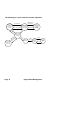
The following depicts the power, mixture and temperature relationships. Best economy range Last cylinder to peak. Use for LOP Lean of Peak leaning 0 50 100 T EG First cylinder to peak.
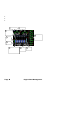
Displays and Controls The EDM monitors engine temperatures and voltages, assists in adjusting the fuel/air mixture, and helps diagnose engine malfunctions. There are three components of the user interface: Analog display including cylinder number and cylinder I.D. box Digital display for numeric readouts and messages Two front panel operating buttons for simple operation.
The following is a description of various display areas. Numbers in circles refer to features in the above diagram. 1 Normalize View and Percentage View Percentage View: when the EGT normalize indicator ‘NRM’ is not lit, the columns indicate percent of EGT red line. Each column is composed of a stack of segments. A maximum height column (all segments lit) depicts 100 %, or more, of red line and a one segment-high column depicts 50 % of red line.
2 Temperature Units (°F or °C) The EDM series engine temps can be set for either degrees Fahrenheit °F or degrees Celsius °C. Note: OAT units can be set independently of the engine temps. To change the display of engine temperatures see “Changing the Alarm Limits” on page 52. 3 Cylinder Numbers and the Cylinder I.D. box The row of numbers 1 through 6 (cylinder I.D numbers) and the letter ‘T’ (optional turbine inlet temp) are the column labels for the analog display bargraphs. A square box (cylinder I.D.
8 TIT Bargraph The EDM provides a bargraph display of the hottest TIT and continuously checks for exceedance of the redline temp. Once redline is reached, the bargraph will change to red and an alert will flash in the Scanner® Information Area. 9 Linear Gauges The Linear gauges provide both digital and analog indications for various parameters.
Typical display configurations by model and mounting orientation The EDM-730/830 series features the ability to be mounted either in landscape or portrait orientation. Display layouts will differ as a result of configuration differences.
EDM-830 RPM and MAP Display The EDM-830 depicts both RPM and Manifold Pressure graphically and digitally. Examples are shown for both landscape and portrait orientation. When a power setting exceeds redline, the digital value changes to red and a blinking message appears in the Scanner® Information Area. Percent horsepower is located in this display area also.
EDM-730/830 Basic Scanner® Operation The EDM-730/830 Scanner section contains graphic representation of EGT, CHT and TIT values as well as containing a general purpose text message area. It will go into Automatic scan mode a few minutes after power up. You don’t have to touch any buttons. CHT redline Digital EGT/CHT/TIT values TIT redline CHT absolute scale Engine temps in F or C Cylinder numbers 1 through 6. T is TIT Cylinder I.D.
TIT: Turbine Inlet Temperature Light Blue segments represent temperature magnitude (at the same scale as EGT) and are located to the right of the last cylinder bar graph set. A ‘T’ just below the dotted line identifies this as TIT. When a white square surrounds the ‘T’, this signifies that the scanner digital values relate to TIT. The digital value is always present above the dotted line and is Light Blue. TIT redline is depicted by a red horizontal line above the majority of the TIT bar graph area.
Button Location and Display Rotation The EDM can be mounted in four different positions. After mounting, you may need to remove and relocate the white button to the ‘STEP’ location. You may also need to rotate the EDM display. Clear any alarms and hold STEP (about 6 seconds) until you see the overlayed arrow. This arrow indicates where the top of the display will be. Tap LF until the arrow points to 12 o’clock. Now tap STEP. Your display should now be upright.
The STEP and LF buttons control all functions of the EDM. The term tap denotes pressing a button momentarily. The term hold denotes pressing and holding a button for five seconds or longer. STEP Button - Primary functions In the Automatic mode, tapping the STEP button will change to the Manual mode. Subsequent taps of the STEP button will display the next parameters in the sequence. In the LeanFind mode tapping the STEP button will terminate the LeanFind mode and change to the Automatic mode.
LF Button - Secondary functions In the pilot programming procedure, holding or tapping the LF button is used to increment or decrement parameter values and toggle between Yes and No answers to questions. STEP and LF buttons together Holding both the STEP and LF buttons simultaneously, for several seconds, changes to the Pilot Programming Mode.
Scanner® Information Area The Scanner® Information Area provides expanded information in the form of alpha-numeric messages, parameters and calculations. In AutoScan, parameters will ‘scan by’ once every 4 seconds (default). This rate can be changed in Pilot Programming Mode. Tap the STEP button for ‘Manual’ selection of any parameter. Parameters for the installed options will be displayed - uninstalled parameters will not appear. DISPLAY EGT 1436 CHT 382 1580 TIT 1490 TI2 204 OIL-T 64 OIL-P 75 CLD 13.
Section 2 - Operating Procedures Built-in Diagnostics: Startup and During Flight When your EDM is first turned on, the screen begins by showing the unit model number and TSO category. Next, several display patterns are presented allowing you to check for proper screen operation. During this time, the EDM is conducting built-in-tests of certain components, calibration and probes. Any newly installed options are found and logged in at this time.
Individual parameters can be excluded from the Automatic mode: tap STEP to enter the Manual mode. Tap STEP to select the parameter you want to exclude. Now tap both STEP and LF buttons simultaneously. Note that tapping the STEP and LF buttons again, toggles back to include status. An excluded parameter displays a decimal point before the parameter name. ‘Excluded’ marker For example: Included: 14.6 BAT Excluded: 14.6 .BAT Every time you turn on the EDM, all parameters are set to ‘included’.
LeanFind Mode The EDM supports two methods of leaning; Rich Of Peak (ROP) and Lean Of Peak (LOP). Note: you can set the power-up default to LOP or ROP in the Pilot Program Mode but easily change modes during flight. During traditional Rich Of Peak leaning, you’ll finalize the mixture to about 20 to 80° rich of peak (depending on engine operating requirements).
Rich of Peak leaning is as simple as: A. Pre-lean your mixture. B. Tap the LF button (verify ROP appears). C. Lean mixture until LEANEST flashes (peak found). D. Enrichen to the desired value ‘Rich Of Peak’. R Procedure 1 Establish cruise at 65 2 to 75% power. Pre-lean the mixture to 50°F estimated rich of peak on any EGT: _________°F. 3 Wait one minute 4 Tap the LF button 5 Lean the mixture at 6 approx. 10°/second without pausing. (cylinder I.D.
Lean of Peak leaning is as simple as: A. Pre-lean your mixture. B. Tap the LF button (verify LOP appears). C. Lean mixture until RICHEST flashes (peak found). D. Enrichen to the desired value ‘Lean Of Peak’. L Procedure Establish cruise 1 2 between 65 to 75% power. Pre-lean the mixture to 50°F estimated rich of peak on any EGT: _________°F. Wait one minute 3 4 Tap the LF button 5 Lean the mixture at 6 7 approx. 10°/second without pausing. (cylinder I.D.
LeanFind Procedure—General Explanation Lycoming and Continental engines have established specific restrictions on leaning that must be followed, such as percentage of power, climb leaning, and TIT limits. Lycoming recommends operation at peak EGT for power settings of 75% or lower, while Continental recommends operation at peak EGT for power settings of 65% or lower. This guide is not meant to supersede any specific recommendations of the engine manufacturer or airframe manufacturer.
Lean Find-Rich Of Peak Detection: Eventually, one cylinder will reach peak before any of the other cylinders. The EDM will determine this automatically. The EDM will indicate success in finding a peak by displaying the word LEANEST for two seconds and flashing the peaked EGT column. The Scanner® Information Area will also display the current value for the peaked EGT on the left, and the word SET on the right (or fuel flow value, if so equipped), for final adjustment of the mixture.
Lean Find-Lean Of Peak Detection: Note: This mode should only be used when your engine is equipped with balanced fuel injectors. When using the Lean of Peak mode, you lean until all EGT’s decrease slightly below their respective peaks. The EDM has automatic peak detection and will sequentially indicate leaning progress. When the first EGT peaks, the word LEANEST appears and the cylinder I.D. box highlights the cylinder number. Each column successively drops as leaning continues.
Expanded Leaning Procedures Lean Of Peak mode: During the ‘lean of peak’ process, the EDM hunts for the last cylinder to peak. This is because, ultimately, you want to have ALL cylinders operating on the lean side of peak. You will final adjust your mixture to this cylinder. To provide a unique graphical depiction during lean of peak operation, the columns become inverted after the first EGT goes just below peak. Each EGT column then originates from the top of the display and drops downward.
Operation for each Phase of Flight Engine Run Up - while RPM is set to run-up value Suggested setup: Normalize view Manual mode . Verify: uniform rise of about 50°F in all EGTs in single magneto operation uniform rise of EGTs with application of the mixture control. Be alert for: unusually low voltage (less than nominal battery voltage) cold OIL abnormally high CHT a higher EGT on one cylinder in dual magneto operation—indicates fouled spark plug.
Cruise - engine stabilized & leaned using LeanFind Suggested setup: Percentage view Automatic mode Descent Suggested setup: Percentage view Manual mode Be alert for: uneven EGTs or CHTs (carbureted engines). Make fine adjustments to throttle, then RPM, then mixture to level the display columns. abnormal patterns of EGTs and CHT. (see “Diagnosing Engine Problems” on page 32). . Be alert for: CLD: shock cooling alarm default is –60°F.
Common Misapplications Some of the more common misapplications made by first-time EDM users are presented here in an attempt to help you avoid similar problems. Problem Situation Corrective action LeanFind finds a ‘peak’ too soon. Failure to pre-lean before performing LeanFind or you stopped leaning. Leaning too slowly. Follow the pre-lean procedure in ‘LeanFind Mode’ section (pg 22). Lean more quickly. Peak not found Lean Find not activated or you stopped leaning.
Section 3 - Diagnosing Engine Problems This chart lists typical EDM indications for most G.A. engines. Parameter EGT at Takeoff EGT in Cruise EGT span (DIF) TIT CHT CHT span OIL Shock cooling (CLD)* Normal range Comments 1200 to 1300°F EGT is approximately 200°F lower than cruise when full throttle applied.
Engine Diagnosis Chart The following chart will help you diagnose engine problems in your aircraft (unit is in ‘Percentage View’ mode for these pictures). Display Symptom Probable Cause Recommended Action 75° to 100° EGT rise for one cylinder during flight Spark plug not firing due to fouling, faulty plug, wire or distributor. Enrich mixture to return EGT to normal. Have plugs checked.
Display Symptom Probable Cause EGT and CHT not uniform Dirty fuel injectors or Check injectors and fouled plugs. plugs. Non-uniformity is normal for carbureted engines Decrease in EGT for all cylinders Decrease in airflow into the induction system. Carb or induction ice. Engine units set to Celsius Slow rise in EGT. Low CHT Check for change in manifold pressure. Check that the alarm limits are set to Celsius degrees Burned exhaust Have compression valve. CHT is low due checked. to low power output.
Display Symptom Probable Cause Recommended Action (no picture) Loss of peak EGT Poor ignition or vapor Have magneto tested. in fuel injection system. (no picture) Decrease in peak or flat EGT response to leaning process Detonation. Usually the result of 80 Octane fuel in 100 Octane engine. Enrich mixture, reduce power and relean mixture. Repeat to find power setting where normal peak is obtained or run rich. Below 10,000 ft. Weak or defective full throttle mechanical fuel causes EGTs to pump.
When an alarm is displayed, tapping the STEP button will temporarily disable the alarm digital indication for the next ten minutes. When an alarm is displayed, holding the STEP button until the word OFF appears will disable that alarm digital indication for the remainder of the flight. See ‘Factory Limits and GPS’ section on page 52 for a list of the alarms and their factory default settings.
Pre-ignition is caused by hot spots in the cylinder. Ignition occurs prior to the spark plug firing. The EDM depicts pre-ignition as a sudden red line of the EGT on the analog display. This may occur in one or more cylinders. The affected cylinder column(s) will flash while the digital display will show an EGT higher than 2000°F. At this temperature pre-ignition will destroy your engine in less than a minute unless you take immediate corrective action.
Start Up Fuel On power-up, you will be prompted to enter any fuel you might have added to the aircraft (this process updates the REMaining and USED values). The EDM will display FUEL for one second, and then flash FILL? N. If you didn’t add any fuel, simply tap STEP to exit, otherwise tap LF and pick one of the three choices below: Choice 1) FILL 66 : This shortcut sets REMaining to the MAIN tank value (you preset MAIN in Factory Limits setup).
Example A: Aircraft has two fuel tanks with internal tabs. You’ve preset: ‘MAIN = 66’ (33 + 33 usable) ‘AUX = 16’ (8 + 8 usable) When you refuel: ‘FILL 66’: use this shortcut when filling to the internal tank tabs. ‘FILL 82’: use this shortcut when filling to the caps.
Example B: Aircraft has two MAIN and two AUX tanks. You’ve preset: ‘MAIN = 60’ (30 + 30 usable) ‘AUX = 14’ (7 + 7 usable) When you refuel: ‘FILL 60’: use this shortcut when filling only MAIN tanks (! AUX tanks must be empty). ‘FILL 74’: use this shortcut when filling MAIN and AUX tanks.
Example C: Aircraft has two MAIN tanks. When you partially refuel, use: ‘FILL +’: use this to add the amount of fuel you pumped into the aircraft (it doesn’t matter which tanks you added to - the EDM totalizes ALL onboard usable fuel). In this example you will add ‘+ 14.0 GAL’, the same as your fuel slip reads. This will be added to the totalizer REM value.
Resetting ‘USED’ Every time you inform the EDM that the aircraft is refueled, the amount of fuel USED is automatically set to zero (unless the instrument is programmed to ACCUM? Y ). To manually zero the amount of fuel USED at any time, manually STEP to display USED and then hold both buttons until the display shows ‘0 USED’ (this normally takes about five seconds. Accumulate — Trip Totalizer To have the USED parameter continuously accumulate total consumed fuel, set ACCUM? Y.
Scanner Parameter Example Table Switch T, A T, A T, A T, A Parameter Example Voltage, System Bus 14.
Section 5 - Long Term Data Memory CAUTION: Do not insert anything but a USB Flash Drive Stick in the USB Port! The EDM compresses and records all displayed parameters once every six seconds in Long Term Data Memory (note: you can change this rate to be 2 to 500 seconds). This data is retrievable by inserting a USB Drive into the jack on the front of the instrument and following the prompts.
The EDM will show messages and percent complete indicators to keep you apprised of progress. When the download is complete the EDM may briefly show DONE. Wait a few seconds for the display to return to the normal engine monitoring mode and then remove your USB Drive. This completes the download. Transferring from the USB Flash Drive to a PC To transfer your data from the USB flash drive to your PC, follow these easy steps. 1. On your PC, start the EzTrends program. 2.
ORIG T ?N NY Select Y if original ship TIT is being used. Tap STEP to accept. If Y chosen, then TIT is calibrated below. TIT +0 TIT +300 TIT -300 OAT F FC Adjust TIT to match ships gauge during flight. Tap STEP to accept and exit PPM. Select degrees F/C. Tap STEP to accept or hold both STEP and LF buttons for a few seconds to access OAT calibration below. OATADJ 0 OAT+I0 OAT-I0 Adjust the indicated temperature up or down by up to 10°. For example, OAT+3 adjusts the OAT 3° higher.
Section 7 - Programming Horsepower Constant For EDM’s equipped with FF, RPM, OAT and MAP, you will adjust the HP Constant once for your aircraft (NOTE: perform MAP adjustment prior to this process) Follow the steps below: 1. Prior to takeoff, with the engine running, enter Pilot Program Mode (hold STEP and LF until ‘PROGRAM’ is displayed). 2. Tap STEP until you see HP ADJUST. Hold both STEP and LF until you see HPC=108 (your value may be different).
window if no ATIS available) by tapping/holding the LF button. The range is +/- 3 in HG. OR B. Airport above sea level: the table below shows MAP for a given field elevation (down the left side of the table) and altimeter setting (along top row of the table). Find the closest entry in the table to your field elevation and current altimeter setting. Interpolate if necessary. Adjust the MAP gauge digital display by tapping/holding LF button. The range is +/- 3 in. HG. Alt setting-> field elev.
RATE 4 ORIG T ?N NY TIT +0 - 975 … + 975 hold STEP and LF buttons simultaneously for several seconds to access the next sequence. Y—Yes—selects factory original TIT probe and proceeds to the next step. Tap the LF button to lower the correction; hold the LF button to raise the correction. For example, if the EDM reads 100 less than the aircraft’s TIT gauge, set the display to read TIT + I00. Tap STEP button to exit the procedure.
1. Make at least three flights of about two to three hours each. Note the actual fuel used (as determined by topping the tanks) and the EDM calculation of the fuel consumed for each flight = USD. Fuel USED shown by EDM (total tank - REM) Flight 1 2 3 Total Actual fuel used by topping tanks 2. Total the EDM fuel used and the actual fuel used. 3. Record the current K factor here ____________________ and in the table below. 4.
6. Tap STEP button for next digit: 18.00 7. Repeat items 5 and 6 for the remaining two digits. 8. Hold STEP and LF buttons until the parameter is saved. Accumulate Total—Trip Total Select this from the Pilot Program Mode. Select ‘N’ if you wish to display total fuel used since the last time you informed the EDM that the aircraft was refueled. Select ‘Y’ to display total fuel used for an extended trip with multiple fuel stops. This selection affects only the USD parameter.
STEP TIME: MNTH: DAY: YEAR: HOUR: MIN: N----- END? Y LF 2 …500 1 … 12 1 …31 00 … 99 00 … 23 00 … 59 N 123456 Comments Record time interval, in seconds Month Day Year (note: represents 2000 through 2099) 24 hour time. We suggest you use Zulu time This also zeros the seconds Current Aircraft ID. To change Aircraft ID, hold both STEP and LF buttons until the first character flashes. LF selects the first character. STEP moves to the next character. To Save, hold both STEP and LF for 5 sec.
The display will then sequence similar to the example chart below. Tap the STEP button to advance to the next item in the list. Tap the LF button to select values for that item. Hold the LF button to increase a numerical value; tap the LF button to decrease a numerical value. The shaded areas in the chart below apply to EDM’s equipped with the Fuel Flow Option.
MAIN=50 GAL KGS LTR LBS 0 … 999 AUX? N NY FUEL GAL AUX=0 MIN =45 0 … 250 0 … 60 REM =10 0 … 200 CARB? N Y RECRD ONLY? Y Y N DATARATE= 9.6 9.6 19.2 CYL=6 Selects the units in all parameters where fuel quantity or fuel rate is displayed 4 … 12 HP = 180 EC =14.90 DISPLAY? 60 … 500 12.00 … 16.
MAP, Fuel Flow Alarm Limits, Units, Fuel Capacity MAP Overboost Alarm Enter the redline for overboost on turbocharged engines. Fuel Flow Units (shaded area above) Selects the units in all measurements where fuel quantity or fuel rate is displayed. If you change this parameter, it does not change the numerical value of the fuel tank capacity. You must do this manually. For example if you change from Gal. to Lbs., the tank capacity will be interpreted as 50 Lbs.
Number of Cylinders This affects only RPM capable EDMs. Set CYL = 4 or 6 depending on your engine. Exceptions: 4 cylinder engine with dual (all-in-one) magnetos set to CYL= 8. 4 cylinder Lasar® ignition set to CYL=8. 6 cylinder Lasar® ignition set to CYL=12. HP and EC Constant settings These adjustments set the parameters for the HP calculations in the EDM. Set the Rated HP for your particular aircraft (for example, a 300 horsepower engine: HP=300).
Navigation GPS Data Formats GPS radios communicate with other equipment in various formats to suite intended usage. You will need to determine what GPS mode is best suited for your installation and set up both your GPS and EDM for compatibility. For incoming GPS data, the EDM automatically configures itself for one of three industry standard data formats, hence there is no EDM selection necessary for the EDM to receive the incoming data.
Diagnostic Messages for Fuel Flow and GPS The following tables depict various messages you may see when a malfunction or signal problem exists: Fuel Flow Transducer Diagnostics 0.0 GPH 0.0 FF --:-- H:M Zeros indicate fuel flow signal is too low to register. ‘FF’ flashing indicates loss of fuel flow signal. Dashes indicate no fuel flow signal. GPS Interface Diagnostics Parameters REQ, RES, MPG are all missing from the scan. NO - COM message and parameters REQ, RES, MPG are missing.
Fuel Data input to GPS (an output from the EDM) RS-232 Serial data format: 8 bit data, 1 start bit, no parity. Baud rate: 9,600. EDM Output format is normally fixed by the GPS-C number you chose, but may be over-ridden when the EDM auto-senses certain incoming GPS navigation formats. For example, if the EDM senses Northstar or NMEA-183 navigation data formats coming in, the EDM will not send fuel data to the GPS. Section 13 - Options Connector Pin Assignments P1 25-pin connector for 4 or 6 cylinder engines.
Section 14 - Display Customization You can customize the linear gauges to your preference. Enter Program Mode, then tap STEP until ‘END? Y’ appears. Hold STEP and LF to enter ‘FAC LIM’ mode. Tap STEP until you see ‘CUSTOMIZE DISPLAY?’. Hold STEP and LF until ‘1=GPH’ appears (GPH may differ on your unit). Tap LF to choose a new function for this position. Tap STEP to accept and move to next position. Repeat until you are satisfied with the choices. Hold STEP and LF to save and exit.
Section 15 - Reference Reading You may wish to know more about the effect of engine operations on EGT and CHT. The reading list below provides general overviews as well as original references on topics that may be of interest. General Overview These references are readily available to pilots and provide a readable source of general technical information. Teledyne Continental Motors, Engine Operation for Pilots, from the FAA Accident Prevention Program, FAA-P-8740-13.
Section 17 - Limited Warranty J.P. Instruments Inc. (JPI) warrants all parts in your new EDM to be free from defects in material and workmanship under normal use. Our obligation under this warranty is limited to repair or exchange of any defective part of this unit if the part is returned, shipping prepaid, within three years for electronics and one year for probes from the date of original purchase. Installation labor is the responsibility of the aircraft owner.
Section 18 - EDM-851 TWIN ENGINE ADDENDUM The following provides instructions for install / operation of the EDM-851 Twin Engine configuration. Each EDM-830 instrument is installed to its respective engine as if it were a single. One EDM operates as a ‘Master’, and the other operates as a ‘Slave’. This allows each instruments fuel computer values, such as total fuel remaining, total fuel used, hours of endurance and so on, to be combined and displayed on the Master.
Section 19 - Index * Pre-leaning procedure:, 25 A Accumulate, 46, 51 total, 42 Adapter probe, CHT, 32 Adjusting K-factor, 49 OAT, 46 TIT, factory original, 48 Alarm Display Lights, 60 Alarm limits changing, 52 factory defaults, 52 fuel flow, 55 Alarms, 35 low fuel, 55 priority, 36 resetting, 36 ALL, 47 select switch, 42 Allied Signal, 57 Automatic indexing mode, 15 Automatic mode, 20 AUX, 54, 56 Auxiliary tanks, 55 Avgas, 36 Aviation data format, 57 B Baud rate, 58 Blinking display, 23, 24, 28, 35, 37 Bri
Download, 44 E Economy, best, 7 EDM-711, 60 EGT alarms, 35 display, 14 loss, 33 probe, 6 resolution, display, 46 select switch, 42 too high, 31, 33 too low, 31, 34 Engine diagnosis chart, 33 run-up, 29 Enunciator, alarm, 35 Exclude parameters, 21 Exhaust leak, 29, 35 EzPlot, 44 F Factory default alarm limits, 52 Factory original TIT probe, 48 Fahrenheit engine temperatures, 53 OAT, 46 Failure to pre-lean, 31 FF, select switch, 42 First cylinder to peak, 25 Flashing display, 23, 24, 28, 35, 37 Flat EGT res
K K-factor changing, 46, 51 determing, 50 KPH, 43 L LBAT, 53 Leak manifold, 35 Leak, manifold, 29 Leanest cylinder, 23, 24 LeanFind button, 17, 18 description, 15 mode, 22 Leaning, 6, See also, LeanFind by TIT, 28 too quickly, 31 LF.
fuel flow option, 49 Stuck valve, 33 Switch, select, 42 R Rate baud, 58 fuel flow, 37, 43 indexing, 49 shock cooling, 30 Real-time, 54 Record, on, off, 54 Recording. See Long Term Memory Option RECRD?, 54 Reference reading, 61 REM, 43 REQ, 43 RES, 43 Reset alarm limits, 52 alarms, 36 Resolution, EGT display, 46 Rich of Peak, 22 Rough engine, 33 RPM display, 13 RS-232, 58 Run-up, 29 S Scanner®, 14 Scanning. See Indexing Select switch, 42 Setting the K factor.
QUICK REFERENCE GUIDE Normalize View 1. Hold LF for three seconds. 2. ‘NRM’ should appear and EGT column heights will center. Percentage View 1. Hold LF for three seconds. 2. ‘NRM’ should disappear and EGT columns will return to absolute temp heights. Automatic Scan 1. Tap LF. 2. Tap STEP. Exclude a Parameter in Auto-Scan 1. Tap STEP to select the parameter to exclude. 2. Tap both STEP and LF. 3. Decimal point appears before parameter name, indicating it is now excluded. Change Auto-Scan Indexing Rate 1.
Filled Tanks Note: if ‘FILL? N’ is visible, start at ‘4.’: 1. Hold both STEP and LF until the display shows PROGRAM, followed by FUEL? N. 2. Tap LF to see FUEL? Y. 3. Tap STEP. 4. See FILL? N. Tap LF to see FILL 75* 5. With aux tanks or tabs, tap LF again to see FILL 120* 6. Tap STEP to accept. Added or Removed Fuel Note: if ‘FILL? N’ is visible, start at ‘4.’: 1. Hold both STEP and LF until the display shows PROGRAM, followed by FUEL? N. 2. Tap LF to see FUEL? Y. 3. Tap STEP. 4. See FILL? N.
Pilot’s Guide Supplement Engine Data Management EDM-740 Experimental Model Copyright 2009 J.P. Instruments, Inc. All Rights Reserved J.P. INSTRUMENTS INC. Information: P. O. Box 7033 Huntington Beach, CA 92646 Factory: 3185 B Airway Costa Mesa, CA 92626 PH: (714) 557-5434 PH: (800) 345-4574 FX: (714) 557-9840 www.jpinstruments.com www.jpitech.com www.BuyJPI.com Support@jpitech.
EDM-740 Pilots Guide Supplemental Information This section describes the added capabilities and operation of the EDM740 model. The added capabilities are: Fuel Pressure: Monitors fuel pressure ranges for either carbureted or injected engines. Fuel pressure is displayed in the ‘Scanner’ area and optionally as a linear gauge via ‘Display Customization’. Sensor type and low and high fuel pressure alarm limits are programmable in the Factory Limits setup area.
EDM-740 Program Mode additional choices Pilot Program Mode additions HOBBS: 1234.9 Displays engine total running hours. Factory Limit Program Mode additions LO AMPS=0 Tap/hold LF to change value. Tap STEP to save. Hold both STEP and LF buttons for a few seconds to access AMP calibration choice below. AMPS ADJ 0 Hold both STEP and LF buttons to enable adjustment. Tap/hold LF to change value. Hold both STEP and LF buttons again to save. HI AMPS=100 Tap/hold LF to change value. Tap STEP to save.
EDM-740 Pilots Guide Supplemental Information EDM-740 Expansion Module pin to sensor assignments J7 Harness Amps Pin / color Shunt Sensor/color Hall Effect Sensor/color 1 (wht) (+)amps ‘WHT’ (wht) 2 (grn) (-)amps (N.U.) 3 (blk) (N.U.) ‘BLK’ (blk) 4 (red) (N.U.) ‘RED’ (red) (N.U.