
Installation Manual User guide

J.P.Instruments
Fuel Flow Installation Manual
Report # 503
for EGT-701 with Fuel Flow Option Page 9 of 14
Rev B : Date 03/14/97
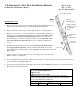
Mounting Procedure:
1. Find a convenient location between the Throttle Body and the Flow Divider and
away from any hot exhaust pipes to suspend the Fuel Flow Transducer.
2. Remove the fuel hose which goes from the Throttle Body to the Flow Divider.
3. Purchase two new hoses, one from the Fuel Servo to the Fuel Flow Transducer
and the other from the Fuel Flow Transducer to the Flow Divider. There must
be flexible hose in and out of the Fuel Transducer. The hoses must meet
TSO-C53a Type C or D FAA specification. The new hoses must be the same
size as the current hose in the aircraft. A source of fittings and fabricated
hoses is:
4.
Mount the Fuel Flow Transducer in the fuel line. The Flow Transducer must
be wrapped with Fire Sleeving.
Place a small hole in the fire sleeve and
pass the transducer wires through it. Seal with High temperature Silicone
RTV sealant.
5. Secure at either end of the transducer to any convenient point on the engine with
MS21919 clamps or equivalent.
6. For Continental fuel injected engines adjust the fuel pressure to account for the pressure drop across the transducer
per Continental Service Bulletin M89-10
7. Cessna 182-T aircraft with an IO-540 engine must use the gravity 700900-2 Transducer if connecting between the
Throttle Body and the Flow Divider.
J.P.INSTRUMENTS
PO Box 7033
Huntington Beach CA 92646
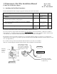
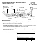
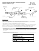
Title Installation of the Fuel Flow Transducer in the fuel line
between the Throttle Body and the Flow Divider. Only applicable
for Continental Fuel Injected Engines
Drawing No. 700922
Date
02/14/97
Drawn/
Approved
Rev NC
OUT
IN
From the Throttle Body
To the Flow Divider
Fittings ¼ NPT to
Fuel Hose (do not
use aluminum
fittings
Aeroquip Fire
Sleeve
AE102/62-24
Aeroquip
900591B Clamp
See note 5
Aeroquuip
303 hose