
Installation Manual User guide
J.P.Instruments
Fuel Flow Installation Manual
Report # 503
for EGT-701 with Fuel Flow Option Page 5 of 14
Rev B : Date 03/14/97
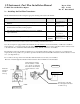
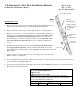
The flow transducer must be mounted so the wires exiting the transducer are pointing up.
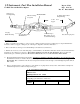
Before connecting any hoses, thoroughly clean them and insure they are free of any loose material. High air pressure my
be used, However, do not allow high air pressure to pass through the flow transducer.
4…. Route the (Optional) External Warning Control Line:
The wire from pin 12 on the J-1 (D-SUB 25) Connector can be connected to an external warning light or buzzer.
This wire grounds when the display flashing a warning is on. The current in this line must be limited to 2/10 of an amp
maximum. Exceeding this limit will damage the unit. If this feature is not used leave this line open. Tie wrap this wire so
it does not obstruct the freedom of travel- controls.
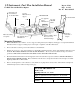
5…. Install the Instrument in the Panel:
(The following section is an excerpt from report #103 Installation
Manual, STC 2586NM)
Locate a 2.25 diameter hole in the instrument panel, where you would like to mount the indicator per drawing 700124. A
steel template supplied with the installation kit is used as a guide for drilling two button holes in the instrument panel. Align
and Mount the Template into the instrument panel hole. First drilling a 0.125 hole. Remove the template and check the
instrument alignment, if OK redrill with a 0.147 drill. The EGT-701(),with Fuel Flow option mounts in a standard 2.25"
instrument hole. The instrument configures itself automatically for 4 to 9 cylinder, 14/28 volt aircraft. The instrument is
7.5” deep less connectors and is 2.6 square behind the panel. To prevent display damage it is essential that the mounting
screws not penetrate the bezel more than .12 inches.
The indicator is FAA TSO approved, as a temperature indicator under TSO-C43b and must be installed in
accordance with STC SA2586NM.
Mount the placard "Do Not Rely on Fuel Flow Instrument to Determine Fuel Levels in Tanks" on the aircraft
instrument panel near the EGT-701(), with fuel flow option. If the aircraft is equipped with a primary fuel flow
instrument, the following placard must be mounted on the aircraft instrument panel near the EGT-701(),with Fuel Flow
option: "Refer to Original Fuel Flow Instrumentation for Primary Information".
6…. Route the Fuel Flow Transducer Wires:
(The following section is an excerpt from report #103 Installation
Manual, STC 2586NM)
Route the thermocouple and fuel flow wires from the probes through the firewall using fireproof rubber grommets and
flame retarding silicone. Use an existing hole if possible. Following the existing wiring harness and connect to the
indicator marking each lead with the cylinder number. All wires must be routed away from high temperature areas
(exhaust stacks, turbochargers, etc.). Secure Probe leads to a convenient location on the engine approximately 8 to 12
inches from the probe, being sure there is sufficient slack to absorb engine torque. It is essential in routing the probe and
fuel flow transducer wires not be allowed to touch metal parts of the air-frame or engine since abrasion will destroy this
wire. Connect wires in accordance with dwg 700744, page 12
7….. System Checkout: Check instrument operation as follows:
1. Turn the aircraft master switch on (engine off) and set the toggle switch to Fuel Flow . Tap the step switch until 0
GPH is displayed. Turn the boost pump on for a few seconds. The display should indicate 3 to 8 GPH.. A problem at
this step could be caused by poor connections on the red or black power and ground leads.
2. Set the instrument toggle switch to "Fuel Flow" and check for a digital fuel flow reading of "00 GPH" indicates the
fuel flow is too low to register. A reading of “ ---GPH “ dashes indicate no fuel flow transducer signals. A problem
at this step could be caused by a poor connection or crossed flow transducer wires.
3. With the engine running, check the "FLOW" Display Mode to read properly. If there is a problem at this point Refer
to EDM-700 Fuel Flow Option Supplement Rev C. Section 4 for troubleshooting information.
4. After running the engine, check the fuel hoses, transducers and fittings for leaks.