
Installation Manual User guide

J.P.Instruments
Fuel Flow Installation Manual
Report # 503
for EGT-701 with Fuel Flow Option Page 3 of 14
Rev B : Date 03/14/97
2…. Initial Check Out
1. The aircraft owner must read the Warranty before starting the installation. There is information in the Warranty that
may alter your decision to install this instrument. If you do not accept the terms of the Warranty, JPI offers a 30
day money back guarantee.
2. If you are not an FAA Certified Aircraft Mechanic familiar with the issues of installing aircraft fuel flow, Do
Not attempt to install this instrument. The installer should use current aircraft standards and practices to install
this instrument (refer to AC 43.13).
3. Check that any necessary FAA Approvals (STC's, etc.) are available for your aircraft before starting the
installation. The FAA Approved Model List (AML) is located at the back of this manual.
4. Read the entire Installation Instructions and resolve any issues you may have before starting the installation.
5. THIS INSTALLATION WILL REQUIRE SOME PARTS UNIQUE TO YOUR AIRCRAFT THAT ARE
NOT SUPPLIED IN THE KIT (including, but not limited to hoses and fittings). Acquire all the parts necessary
to install this instrument before starting the installation. Do not use aluminum fittings with the FXT-201 or FXT-231
transducer.
6. Check that the instrument make and model are correct before starting the installation (check the markings on the side
of the instrument). A gravity feed system requires an FXT-231 flow transducer (marked "231" on top). A carbureted
engine with a fuel return line requires an FFDM-I, -2 , which can be purchased from Electronics International, or
J.P.Instruments.
7. Before starting the installation make sure the unit will fit in the location you intend using. Refer to J.P.Instruments
installation report 103, for the EGT-701, temperature indicator , STC SA 2586NM.
8. If this instrument is to replace an existing unit in the aircraft, it is the installer's responsibility to move or replace any
existing instruments or components in accordance with FAA approved methods and procedures. The following
Installation Instructions do not cover moving or the removal of any existing instruments or components.
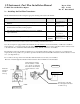
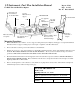
9. Before connecting any hoses to the transducer, thoroughly clean them and insure they are free of any loose material.
Never pass high pressure air through or blow through the transducer, damage will occur.
10. Remove the transducer cap plugs when ready to install hoses. Do not use aluminum fittings with the fuel flow
transducer or Gauling may occur.
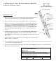
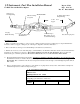
11. Note the direction of fuel flow marked on the transducer. Fuel must flow in this direction.
12. Mount the transducer with the three wires pointing up.
13. Note and record the K-factor engraved in the side of the transducer.
14. Do not use teflon tape or thread sealent compound of any kind.