
Installation Manual User guide

J.P.Instruments
Fuel Flow Installation Manual
Report # 503
for EGT-701 with Fuel Flow Option Page 14 of 14
Rev B : Date 03/14/97
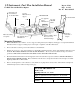
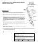
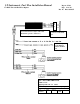
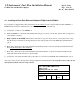
10.. Installing the Fuel Flow Differential Module FFDM-I and the FFDM-2:
If your engine is equipped with a fuel return line from the carburetor back to the fuel tank, install the FFDM-1 or
FFDM-2 in the aircraft as outlined below (see sheet one ). Otherwise, omit this step.
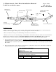
a) Connect the connector to the FFDM-I, -2
b) Install the FFDM-1, -2 under the instrument panel using two tie wraps on each end of the module to support it to
a wire bundle or bracket.
c) Only required on the FFDM-1. Route and connect the 3' red power lead to the 12 or 24 volt bus via a 1 amp
fuse. Route and connect the 3' black ground lead to the same ground used for the EGT-701(),with Fuel Flow
option.
d) Route and connect the 6' red, black and white leads marked "Feed" to the flow transducer installed in the fuel
line from the fuel pump to the carburetor.
e) Route and connect the 6' red, black and white leads marked "Return" to the flow transducer installed in the
return fuel line from the carburetor to the fuel tank.
f) Connect the red, black and white leads to the same color 6' leads from the EGT-701(),with Fuel Flow option.
Any excess wires can be rolled up and tie wrapped under the instrument panel. Tie wrap these wires so they do not
obstruct the freedom of travel of any controls.
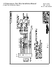
J.P.INSTRUMENTS
PO Box 7033
Huntington Beach CA 92646
Title: FFDM-1 Interconnect Wiring Diagram
Drawing No. 700920
Date
02/14/97
Drawn
Approved
Sheet
2 of 2
Rev NC