
User Manual


Pg. 21
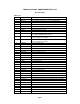
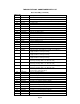
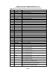
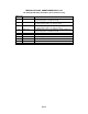
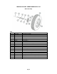
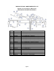
TORSION-FLEX SOIL CONDITIONER PARTS LIST
Base Assembly
PARTS LIST
Item # Part # Description
1 BMF-2-12 Base Unit Main Frame (TF2 – 12’ or 13’ working width)
1 BMF-2-14 Base Unit Main Frame (TF2 – 14’ or 15’ working width)
1 BMF-2-16 Base Unit Main Frame (TF2 – 16’ or 17’ working width)
1 BMF-2-18 Base Unit Main Frame (TF2 – 18’ working width)
1 BMF-212 Base Unit Main Frame (TF212)
1 BMF-215 Base Unit Main Frame (TF215)
2 WAW-1 Wheel Arm Weldment (TF2)
2 WAW-2 Wheel Arm Weldment (TF212 or TF215)
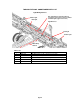
3 38HC 3” x 8” Hydraulic Cylinder (left or right side wheel cylinder on
units equipped WITHOUT wing wheels)
3 3148HCMS 3 1/4” x 8” MS Hydraulic Cylinder (for units equipped WITH wing
wheels) (32TP08-125 639706)
3 3128HCMS 3 1/2" x 8” MS Hydraulic Cylinder (for units equipped WITH wing
wheels) (35TP08-125 639707)
4 1149G5B 1 1/4" x 9” Grade 5 Bolt
5 114NLN 1 1/4" Nylon Lock Nut
6 1312P 1” x 3 1/2" Pin
7 CP-316 3/16” Cotter Pin
8 CYLK-2 Cylinder Lock
9 38212WLP 3/8” x 2 1/2" Wire Lock Pin
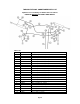
10 21220TFA 2 1/2” x 2 1/2” x 2’ 0” Torsion-Flex Arm (units under 25’ wide)
10 3330TFA 3” x 3” x 3’ 0” Torsion-Flex Arm (TF212 units 25’ to 36’ wide)
10 3320TFA 3” x 3” x 2’-0” Torsion-Flex Arm (TF215)
11 SWB-1 Swivel Bracket
12 16G5B 1” x 6" Grade 5 Bolt
13 1G5LN 1” Grade 5 Lock Nut
14 584512UB 5/8” x 4” x 5 1/2" U-Bolt
15 5844UB 5/8” x 4” x 4” U-Bolt
16 58G5LN 5/8” Grade 5 Lock Nut
17 12312G5B 1/2" x 3 1/2" Grade 5 Bolt
18 12G5LN 1/2" Grade 5 Lock Nut
19 134514G5B 1 3/4" x 5 1/4" Grade 5 Bolt
20 HN-134 1 3/4” Hex Nut
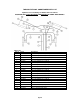
22 LA-2TF24 Leverage Arm (round hole) (for working widths 24’ and smaller)
22 LA-2TF212 Leverage Arm (oblong hole) (for model TF212, 25’ to 36’ wide)
22 LA-2TF215 Leverage Arm (for model TF215)
23 PLA-2 Pivot Linkage Arm (TF212)
23 PLA-2L Pivot Linkage Arm, Long (TF215)
24 1344P 1 3/4" x 4” Pin
25 716234RP 7/16” x 2 3/4" Roll Pin
26 424HC 4” x 24” Hydraulic Cylinder (TF212)
26 430HC 4” x 30” Hydraulic Cylinder (TF215)