OPERATOR’S MANUAL Set-Up Instructions and Parts Catalog for Torsion-Flex Soil Conditioners Models TF2, TF212 and TF215 (serial # 2250 and higher) 12’ to 45’ Working Width Torsion-Flex Double Rolling Baskets J. & M. Manufacturing Co., Inc. P.O. Box 547 Fort Recovery, OH 45846 Phone: (419) 375 2376 Fax: (419) 375-2708 E-mail: sales@jm-inc.com Website: www.jm-inc.com REV. 03-28-11 Pg.
TO THE DEALER: Read manual instructions and safety rules. Make sure all items on the Dealer’s Pre-Delivery and Delivery Check Lists in the Operator’s Manual are completed before releasing equipment to the owner. The dealer must complete the Warranty Registration Card attached to the front inside cover of this manual and return to J. & M. Mfg. Co., Inc. at the address indicated on the card. Warranty claims will be denied if the Warranty Registration Card has not been completed and returned.
GENERAL INFORMATION TO THE OWNER: The purpose of this manual is to assist you in operating and maintaining your running gear in a safe manner. Read it carefully. It furnishes information and instructions that will help you achieve years of dependable performance and help maintain safe operating conditions. If this machine is used by an employee or is loaned or rented, make certain that the operator(s), prior to operating: 1. Is instructed in safe and proper use. 2.
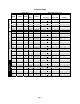
GENERAL INFORMATION (continued) BOLT TORQUE CHART Always tighten hardware to these values unless a different torque or tightening procedure is listed for a specific application. Fasteners must always be replaced with the same grade as specified in the manual parts list. Always use the proper tool for tightening hardware. hardware. SAE for SAE hardware and Metric for metric Make sure fastener threads are clean and you start the thread engagement properly.
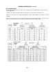
SPECIFICATIONS Model TF215 Model TF212 Model TF2 Specifications Basket Sizes and Layout Working Width Transport Width Base Width Wing s Each Approx. Weight 12’ 12’ 12’ N/A 13’ 13’ 12’ N/A 2,310 lbs. 4’ 5’ 4’ 14’ 14’ 12’ N/A 2,425 lbs. 5’ 4’ 5’ 15’ 15’ 15’ N/A 2,540 lbs. 5’ 5’ 5’ Side Wing Base Unit 2,195 lbs. 6’ 16’ 16’ 15’ N/A 2,655 lbs. 5’ 6’ 5’ 17’ 17’ 15’ N/A 2,770 lbs. 6’ 5’ 6’ 6’ 6’ 18’ 18’ 15’ N/A 2,885 lbs.
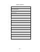
TABLE OF CONTENTS WARRANTY 2 GENERAL INFORMATION 3 BOLT TORQUE CHART 4 SPECIFICATIONS 5 SAFETY RULES 7 SAFETY SIGNS 8 SET-UP INSTRUCTIONS 9-15 OPERATIONS 16 TRANSPORTING 17 UNHITCHING 17 FIELD ADJUSTMENT 17 STORAGE 18 SERVICE 18 TROUBLESHOOTING 18 PARTS LIST TONGUE ASSEMBLY 19 BASE ASSEMBLY 20-23 WING ASSEMBLY 24-25 WHEEL ASSEMBLY 26 LIGHT WIRING DIAGRAM 27 HYDRAULIC LINES AND FITTINGS Models TF212 and TF215 Without Wing Wheels 28-29 Models TF212 and TF215 With Wing W
SAFETY RULES ATTENTION! BECOME ALERT! YOUR SAFETY IS INVOLVED! Safety is a primary concern in the design and manufacture of our products. Unfortunately, our efforts to provide safe equipment can be erased by an operator’s single careless act. In addition, hazard control and accident prevention are dependent upon the awareness, concern, judgment, and proper training of personnel involved in the operation, transport, maintenance and storage of equipment.
SAFETY SIGNS IMPORTANT: Install new safety signs if the old signs are destroyed, lost, painted over or cannot be read. When parts are replaced that have safety signs, make sure you install a new sign with each new part. New signs are available from the manufacturer or your authorized dealer.
SET-UP INSTRUCTIONS The J&M Torsion-Flex Soil Conditioner is shipped with components partially assembled. Hardware required to connect the Base Wheel Assembly, Main Base Frame Assembly, Wing Frames and Tongue Assembly should already be secured to the components at the point of attachment. The hydraulic cylinders have the fittings already installed and are secured to the base wheel assembly.
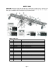
SET-UP INSTRUCTIONS Turn Buckle Assembly Step 1 – Installing the Base Unit Wheels Using the 1” x 3 1/2" Pins and cotter pins, secure the two wheel lift hydraulic cylinders to the tabs welded on the front of the Base Unit Main Frame. (NOTE: For implements equipped with wing wheels, be sure a 3” MS hydraulic cylinder is used on the right set of wheels and a 2 3/4" MS hydraulic cylinder is used for the left set of wheels.
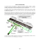
SET-UP INSTRUCTIONS 5/8” x 4” x 5 1/2” U-Bolts Step 4 – Installing the Base Unit Baskets Secure the torsion-flex arm of the rolling basket assembly to the rear tubing member of the Base Unit Main Frame using two 5/8” x 4” x 5 1/2" UBolts and 5/8” Lock Nuts. Make sure the baskets are symmetrically placed on the Base Unit Main Frame and have a 1 1/2” clearance between baskets.
SET-UP INSTRUCTIONS Step 7 – Installing the Wing Baskets Secure the torsion-flex arm of the rolling basket assembly to the rear tubing member of the Wing Frame using two 5/8” x 4” x 5 1/2" U-Bolts and 5/8” Lock Nuts. Make sure the wing baskets are placed according to the “Basket Sizes and Layout” section of the chart found on page 5. IMPORTANT: Make sure the wing baskets closest to the baskets on the Base Unit baskets have a clearance of 2”.
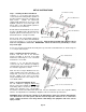
SET-UP INSTRUCTIONS INSTALLING OPTIONAL WING WHEELS For soil conditioners equipped with side wing wheels, mount the Wing Arm Mount Bracket to the front tubing member of the Wing Frame as shown (approximately 6” from the end of the wing frame) using two 1/2" x 5” Grade 5 Bolts and 1/2" Lock Nuts. Bolt the Wheel Arm Weldments to the front of the Base Unit Main Frame directly below the hydraulic cylinder shown using one 1 1/4" x 9” Grade 5 Bolt and 1 1/4" Nylon Lock Nut.
SET-UP INSTRUCTIONS ADJUSTING THE PRESET VALVE ON THE FOLDING WING CYLINDER (continued) NOTE: Be sure the baskets are free from excessive mud, rocks or debris before beginning the folding/unfolding sequence. Excessive weight could effect the timing of the folding sequence, causing possible collision. WARNING: Charge the cylinders with hydraulic oil to bleed all air out of the system, and then check for any leaks.
To Install the Coil Tine Spring Assembly Slide the Coil Tine Springs (#22) around the Coil Tine Pipe (#21) and secure at each hole location using the 1/2” x 3 1/2” J-Bolt (#23) and 1/2” Lock Nut (#16). Repeat for each pipe. Secure the Coil Tine Pipe to the pivot brackets on the lower end of the harrow arm using the two Squeeze Blocks (#19) and four 1/2” x 4 1/2” Grade 5 Bolt (#20) with 1/2” Lock Nuts (#16).
OPERATIONS PREPARING THE TORSION-FLEX SOIL CONDITIONER Before putting the soil conditioner into operation, check the machine for damaged or worn parts and replace as necessary. Hardware Make sure all hardware is properly fastened according to the Bolt Torque chart found in this manual. Recheck all hardware for tightness after the unit has been operated for several hours. Check all pins and retaining rings are in good condition. Replace any pins of retaining rings that are worn, damaged or missing.
TRANSPORTING Before the soil conditioner is transported, be sure to secure the Jack Assembly in the transport position located on the top of the Storage Extension Arm. The Torsion-Flex Soil Conditioner will increase the overall length of the primary tillage tool. Use extreme caution when turning to avoid obstacles. Reduce ground speed as necessary to maintain control of equipment. Install hydraulic cylinder transport locks on the Base Unit wheels BEFORE transporting.
STORAGE To add longer service and life to your Torsion-Flex Soil Conditioner, perform the following before placing the implement in storage: 1. 2. 3. 4. 5. 6. 7. 8. Remove dirt and trash that may cause rusting. Repaint any areas where the paint has been chipped, scratched or worn away. Coat all earth moving surfaces with a suitable rust preventative. Inspect for damaged or worn parts and replace before next use. Lubricate wing and wheel pivot points.
TORSION-FLEX SOIL CONDITIONER PARTS LIST Tongue Assembly PARTS LIST Item # Part # Description 1 AFTW-2 A-Frame Tongue Weldment (TF2) 1 AFTW-212 A-Frame Tongue Weldment (TF212) 1 AFTW-215 A-Frame Tongue Weldment (TF215) 2 ITW-TF1 Inner Tongue Weldment 3 12HHR 1/2” Hose Holder Rod 4 3834G5B 3/8” x 3/4" Grade 5 Bolt 5 18PCP 1” x 8” Tongue Pin 6 CP-316 Cotter Pin 7 1146G5B 1 1/4" x 6” Grade 5 Bolt 8 HLN-114 1 1/4" Hex Nut Pg.
TORSION-FLEX SOIL CONDITIONER PARTS LIST Base Assembly Pg.
TORSION-FLEX SOIL CONDITIONER PARTS LIST Base Assembly PARTS LIST Item # Part # Description 1 BMF-2-12 Base Unit Main Frame (TF2 – 12’ or 13’ working width) 1 BMF-2-14 Base Unit Main Frame (TF2 – 14’ or 15’ working width) 1 BMF-2-16 Base Unit Main Frame (TF2 – 16’ or 17’ working width) 1 BMF-2-18 Base Unit Main Frame (TF2 – 18’ working width) 1 BMF-212 Base Unit Main Frame (TF212) 1 BMF-215 Base Unit Main Frame (TF215) 2 WAW-1 Wheel Arm Weldment (TF2) 2 WAW-2 Wheel Arm Weldment (TF2
TORSION-FLEX SOIL CONDITIONER PARTS LIST Base Assembly (continued) PARTS LIST Item # Part # Description 27 TBCB-1 Turn Buckle Center Pipe 28 TBS-2RH Turn Buckle Shaft (both ends R/H thread) 28 TBS-1RH1LH Turn Buckle Shaft (1 end L/H thread; 1 end R/H thread) 29 HN-114 1 1/4" Hex Nut 30 CE-2 Turn Buckle Clevis End 31 TBW-1 Turn Buckle Wrench 32 LP-1 Lynch Pin 33 SEA-1 Storage Extension Arm 34 12412G5B 1/2" x 4 1/2" Grade 5 Bolt 35 JSA-TF Jack Stand Assembly 36 JSA-P1 Jack St
TORSION-FLEX SOIL CONDITIONER PARTS LIST Base Assembly (continued) PARTS LIST Item # Part # Description 62 LW-114 1 1/4” Lock Washer 63 121PS 1/2” x 1” Pipe Spacer TORSION-FLEX SOIL CONDITIONER PARTS LIST Wing Assembly Pg.
TORSION-FLEX SOIL CONDITIONER PARTS LIST Left and Right Side Wing Assemblies (TF212 and TF215 only) PARTS LIST Item # Part # Description 1 WF-212-4 Wing Frame (TF212) (4’ L) 1 WF-212-5 Wing Frame (TF212) (5’ L) 1 WF-212-6 Wing Frame (TF212) (6’ L) 1 WF-212-7 Wing Frame (TF212) (7’ L) 1 WF-212-8 Wing Frame (TF212) (8’ L) 1 WF-212-9 Wing Frame (TF212) (9’ L) 1 WF-212-10 Wing Frame (TF212) (10’ L) 1 WF-212-11 Wing Frame (TF212) (11’ L) 1 WF-212-12 Wing Frame (TF212) (12’ L) 1 WF-2
TORSION-FLEX SOIL CONDITIONER PARTS LIST Left and Right Side Wing Assemblies (TF212 and TF215 only) PARTS LIST Item # Part # Description 16 RB40-4-114 4’ Rolling Basket (used on soil conditioners equipped with 4-hole flange bearings with 1 1/4” diameter shaft) 16 RB50-4-114 4’ 6” Rolling Basket (used on soil conditioners equipped with 4hole flange bearings with 1 1/4” diameter shaft) 16 RB56-4-114 5’ 6” Rolling Basket (used on soil conditioners equipped with 4hole flange bearings with 1 1/4” diame
TORSION-FLEX SOIL CONDITIONER PARTS LIST Wheel Assembly PARTS LIST Item # Part # Description 1 SS-134SC 1 3/4" Diameter Spindle 2 CP-316 Cotter Pin 3 103953 Grease Seal 4 104579 Cone (large) 104579 or LM-48548 5 104082 Cone (small) 104082 or LM-67048 6 104581 Spindle Washer 7 103289 Slotted Spindle Nut 8 105218 Hub with Studs, Nuts and Cups 9 5552 Wheel Nut 10 4187 Wheel Stud 11 103969 Dust Cap 12 1633 Grease Fitting 13 WR-156-6 Wheel Rim, 15” x 6” – 6 hole (WR-SC2)
TORSION-FLEX SOIL CONDITIONER PARTS LIST Light Wiring Harness Run Light Harness through tubing at grommet locations and connect to Amber and Red Lights (typical each side) Amber Light Red Light Light Enhancer Red Light Amber Light Main Wiring Harness PARTS LIST Item # Part # Description 1 MWH-TF2 Main Wiring Harness with 7-Prong Connector End 2 LWH-TF2 Light Wiring Harness (from enhancer to red and amber lights) 3 LE-1B Light Enhancer (connects main wiring harness with rear lights) GR-134 1
TORSION-FLEX SOIL CONDITIONER PARTS LIST Hydraulic Lines and Fittings for Models TF212 and TF215 EQUIPPED WITHOUT OPTIONAL WING WHEELS PARTS LIST Item # Part # Description 1 HH-38336 3/8” x 336” Hydraulic Hose (TF212) 1 HH-38384 3/8” x 384” Hydraulic Hose (TF215) 2 HH-3866 3/8” x 66” Hydraulic Hose (TF212) 2 HH-3875 3/8” x 75” Hydraulic Hose (TF215) 3 HH-3843 3/8” x 43” Hydraulic Hose (TF212) 3 HH-3832 3/8” x 32” Hydraulic Hose (TF215) 4 HH-3840 3/8” x 40” Hydraulic Hose with swivel e
TORSION-FLEX SOIL CONDITIONER PARTS LIST Hydraulic Lines and Fittings for Models TF212 and TF215 EQUIPPED WITH 2-SETS OF HOSES AND WITHOUT OPTIONAL WING WHEELS PARTS LIST Item # Part # Description 1 HH-38336 3/8” x 336” Hydraulic Hose (TF212) 1 HH-38384 3/8” x 384” Hydraulic Hose (TF215) 2 HH-3877 3/8” x 77” Hydraulic Hose (TF212) 2 HH-3889 3/8” x 89” Hydraulic Hose (TF215) 3 HH-3865 3/8” x 65” Hydraulic Hose (TF212) 3 HH-3877 3/8” x 77” Hydraulic Hose (TF215) 4 HH-3832 3/8” x 32” Hyd
TORSION-FLEX SOIL CONDITIONER PARTS LIST Hydraulic Lines and Fittings for Model TF212 EQUIPPED WITH OPTIONAL WING WHEELS PARTS LIST Item # Part # Description 1 HH-12336 1/2” x 336” Hydraulic Hose 2 HH-38210 3/8” x 210” Hydraulic Hose (TF212-32, TF212-33) 2 HH-38222 3/8” x 222” Hydraulic Hose (TF212-34, TF212-35) 2 HH-38234 3/8” x 234” Hydraulic Hose (TF212-36) 3 HH-38174 3/8” x 174” Hydraulic Hose (TF212-32, TF212-33) 3 HH-38186 3/8” x 186” Hydraulic Hose (TF212-34, TF212-35) 3 HH-3819
TORSION-FLEX SOIL CONDITIONER PARTS LIST Hydraulic Lines and Fittings for Model TF215 EQUIPPED WITH OPTIONAL WING WHEELS PARTS LIST Item # Part # Description 1 HH-38384 3/8” x 384” Hydraulic Hose 2 HH-38234 3/8” x 234” Hydraulic Hose (TF215-37, TF215-38) 2 HH-38246 3/8” x 246” Hydraulic Hose (TF215-39, TF215-40) 2 HH-38258 3/8” x 258” Hydraulic Hose (TF215-41, TF215-42) 2 HH-38270 3/8” x 270” Hydraulic Hose (TF215-43, TF215-44, TF215-45) 3 HH-38198 3/8” x 198” Hydraulic Hose (TF215-37, T
TORSION-FLEX SOIL CONDITIONER PARTS LIST Hydraulic lines and Fittings for Model TF212 EQUIPPED WITH OPTIONAL WING WHEELS (Since August 2010) Item # 1 2 2 2 3 3 3 4 4 4 5 6 7 8 9 10 11 12 13 14 15 Part # HH‐38336 HH‐38210 HH‐38222 HH‐38234 HH‐38174 HH‐38186 HH‐38198 HH‐38162 HH‐38174 HH‐38186 HH‐3862 HH‐3834 HH‐3829 HH‐38112 38M38F 38T‐FFM 106521 106522 38M38F‐O 106523 103524 Description 1/2" x 336" Hydraulic Hose 3/8" x 210" Hydraulic Hose (TF212‐32, TF212‐33) 3/8" x 222" Hydraulic Hose (TF212‐34, TF212‐
TORSION-FLEX SOIL CONDITIONER PARTS LIST Hydraulic Lines and Fittings for Model TF2 (12’ to 18’ Working Width) PARTS LIST Item # Part # Description 1 HH-38264 3/8” x 264” Hydraulic Hose 2 HH-3877 3/8” x 77” Hydraulic Hose 3 HH-3844 3/8” x 44” Hydraulic Hose 4 HH-3832 3/8” x 32” Hydraulic Hose 5 HH-3865 3/8” x 65” Hydraulic Hose 6 38T3F Tee, 3/8” Female (3) 7 12M38F Elbow, 1/2” Male, 3/8” Female Pg.
TORSION-FLEX SOIL CONDITIONER PARTS LIST Optional Wing Wheel Assembly PARTS LIST Item # Part # Description 1 WAW-2L Wing Arm Weldment (left) 1 WMB-2R Wing Arm Weldment (right) 2 WMB-2 Wing Arm Mount Bracket 3 125GR5B 1/2" x 5” Grade 5 Bolt 4 12LN 1/2" Lock Nut 5 1149G5B 1 1/4" x 9” Grade 5 Bolt 6 114NLN 1 1/4" Nylon Lock Nut 7 12312G5B 1/2" x 3 1/2" Grade 5 Bolt 8 12G5LN 1/2" Grade 5 Lock Nut 9 3348HCMS 3 3/4” x 8” Hydraulic Cylinder (37TP08-137 639708) 9 38HCMS 3” x 8” Hy
TORSION-FLEX SOIL CONDITIONER PARTS LIST Optional Leveling Harrow REAR FRONT REAR FRONT Pg.
TORSION-FLEX SOIL CONDITIONER PARTS LIST Optional Leveling Harrow # PARTS LIST Part # Description # Part # Description 1 321HA 3” x 21” Harrow Arm 14 3415RB 3/4” x 15” Round Bar 2 21246MB 2 1/2” x 4” x 6” Mounting Bracket 15 1244UB 1/2” x 4” x 4” U-Bolt 3 584512UB 5/8” x 4” x 5 1/2” U-Bolt 16 12LN 1/2” Lock Nut 4 58LN 5/8” Lock Nut 17 12112G5B 1/2” x 1 1/2” Grade 5 Bolt 5 346G5B 3/4” x 6” Grade 5 Bolt 18 12214W 1/2” x 2 1/4” Oversized Washer 6 34LN 3/4” Lock Nut 19 HS
SERVICE / MAINTENANCE RECORD Date Description Notes Pg.