OPERATOR’S MANUAL Set-Up Instructions and Parts Catalog for Model HT-1082 Low Profile Header Transports J. & M. Manufacturing Co., Inc. P.O. Box 547 Fort Recovery, OH 45846 Phone: (419) 375 2376 Fax: (419) 375-2708 E-mail: sales@jm-inc.com Website: www.jm-inc.com REV-03-30-09 Pg.
TO THE DEALER: Read manual instructions and safety rules. Make sure all items on the Dealer’s Pre-Delivery and Delivery Check Lists in the Operator’s Manual are completed before releasing equipment to the owner. The dealer must complete the Warranty Registration Card attached to the front inside cover of this manual and return to J. & M. Mfg. Co., Inc. at the address indicated on the card. Warranty claims will be denied if the Warranty Registration Card has not been completed and returned.
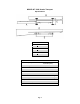
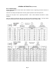
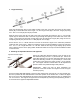
MODEL HT-1082 Header Transport Specifications A B C D E DIMENSIONS HT-1082 19’-0” 34’-0” – 50’-0” 6’-10” 48’-0” – 56’-0” 18’-6” SPECIFICATIONS Capacity 16,000 lbs. (Gross) 13,500 lbs. (Net) Weight 2,340 lbs. Wheel Size 16” x 6” Tire Size 235/85R16F Hubs 6 bolt Spindles 2” diameter Main Frame 4” x 8” x 3/16” steel tubing Steel Upper Bar 4” x 8” x 3/16” steel tubing Adj. Header Mounts Standard Tie Down Straps Standard Pg.
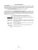
GENERAL INFORMATION TO THE OWNER: The purpose of this manual is to assist you in operating and maintaining your running gear in a safe manner. Read it carefully. It furnishes information and instructions that will help you achieve years of dependable performance and help maintain safe operating conditions. If this machine is used by an employee or is loaned or rented, make certain that the operator(s), prior to operating: 1. Is instructed in safe and proper use. 2.
GENERAL INFORMATION (continued) BOLT TORQUE CHART Always tighten hardware to these values unless a different torque or tightening procedure is listed for a specific application. Fasteners must always be replaced with the same grade as specified in the manual parts list. Always use the proper tool for tightening hardware. hardware. SAE for SAE hardware and Metric for metric Make sure fastener threads are clean and you start the thread engagement properly.
TABLE OF CONTENTS INTRODUCTION 2 EXPRESS WARRANTY 2 SPECIFICATIONS 3 GENERAL INFORMATION 4 BOLT TORQUE CHART 5 SAFETY RULES 7 SAFETY 7 SAFETY SIGNS 8 SET-UP INSTRUCTIONS 8-12 REPAIR PARTS LIST Main Frame and Upper Bar 13 Front Axle Assembly 13 Tie-Down Bracket and Adjustable Header Mount 14 Adjustable Upper Bar Mount 14 Rear Axle Assembly 15 Rear Fender Assembly 15 Light Kit 16 INITIAL OPERATION / MAINTENANCE 17 SERVICE / MAINTENANCE RECORD 18 Pg.
SAFETY RULES ATTENTION! BECOME ALERT! YOUR SAFETY IS INVOLVED! Safety is a primary concern in the design and manufacture of our products. Unfortunately, our efforts to provide safe equipment can be erased by an operator’s single careless act. In addition, hazard control and accident prevention are dependent upon the awareness, concern, judgment, and proper training of personnel involved in the operation, transport, maintenance and storage of equipment.
SAFETY SIGNS ATTENTION: BECOME ALERT! YOUR SAFETY IS INVOLVED! Replace Immediately If Damaged or Missing! IMPORTANT: Install new safety signs if the old signs are destroyed, lost, painted over or cannot be read. When parts are replaced that have safety signs, make sure you install a new sign with each new part. New signs are available from the manufacturer or your authorized dealer.
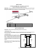
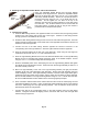
3. Tongue Assembly Place the Small Spring (#3) into the holder located at the front of the latch and insert the two spacer blocks (#4) on each side of the inner tongue. Pin the Tongue Latch (#2) to the Inner Tongue (#1) using the 1” dia. x 5 3/4” Pin (#5) and roll pin provided. Slide the inner tongue into the front half of the Outer Tongue (#6) and insert the 7/8” x 2 1/4” bolt with spacer (#7) into the bottom side of the inner tongue through the opening on the bottom side of the outer tongue.
5. Attaching the Adjustable Header Mounts and Tie-Down Brackets Place the Adjustable Header Mounts and Tie-Down Bracket Assemblies on the large lower bar. Secure the Adjustable Header Mount to the large lower tube using one 3/4” x 6 1/2” Stove Bolt Adjustable and Clamp Handle Assembly. Secure the Tie-Down Bracket to Header the large lower tube using two 1/2” x 5 1/2” Bolts and two 1/2” Mount Lock Nuts.
PARTS LIST Main Frame and Upper Bar # 1 Part # UB-24H Description 48' L Upper Bar (two 24' L bars with splice plate) 1 1 1 1 2 3 SP-24H UB-42H UB-38H UB-32H SLB-1082 LLB-1082 Splice Plate for 24' Upper Bar 42' L Upper Bar 38' L Upper Bar 32' L Upper Bar 4" x 6" Small Lower Bar (HT-1082) 4" x 8" Large Lower Bar (HT1082) # 4 5 6 7 8 9 Part # 586G8B 58-FW 58LN 12312B 12-W 12-LN Description 5/8" x 6" Grade 8 Bolt 5/8" Flat Washer 5/8" Lock Nut 1/2" x 3 1/2" Bolt for Splice Plate 1/2" Regular Washer 1/2
PARTS LIST Front and Rear Axle Assembly # 1 Part # FA-1082 Description Front Axle Only, Less Hub and Spindle Assembly and Hitch 2 3 4 5 6 7 8 8 9 10 11 12 13 14 15 16 RA-1082 SPB-134 HN-134 KP-1082 HN-114 HW-1082 SA-1082L SA-1082R 106166 105771 106164 105144 104082 104581 103289 CP-316 Rear Axle Only, Less Hub Assy Spindle Bolt, 1 3/4" x 13 1/2"L 1 3/4" Hex Nut 1 1/4" King Pin Vertical Hitch Bolt 1 1/4" Hex Nut Hitch Weldment 2" Spindle and "U" Assy (left) 2" Spindle and "U" Assy (right) Grease Seal C
PARTS LIST Tie-Down Bracket and Adjustable Header Mount # 1 2 2 2 Part # AB-L2 AB-U2L AB-U2R AB-U2L-MD 2 3 4 5 6 7 8 9 9 AB-U2RMD CHA2 CB58612 3412P HC-CP TDMB-2 RA-1 TDS-1 TDS-1L 10 11 12 13 12512G5B 12LN 12234G5B 12NLN Description Lower Adjustable Bracket Upper Adjustable, Bracket (L/H) Upper Adjustable, Bracket (R/H) Upper Adj. Bracket (L/H) (MacDon) Upper Adj.
PARTS LIST Light Kit # 1 2 3 4 5 6 7 8 9 10 11 12 13 Part # EB-1 AIS-2 127-HB 12-N LMB-1 TA-1 HDN-12 12114-G5FB 12-FN RLT-R RLT-L 38STS SMV-1 Description Extension Bracket Angle Iron Support 1/2" x 7" Hex Bolt 1/2" Nut Light Mounting Bracket Telescoping Arm 1/2" Handle Nut 1/2" x 1 1/4" Grade 5 Flange Bolt # 14 15 16 17 18 19 20 21 Part # 141-CB 14-W 14LN RD-A1 RD-R1 RD-O1 LWH-1 LE-1B Description 1/4" x 1" Bolt 1/4" Washer 1/4" Lock Nut Amber Reflective Decal Red Reflective Decal Orange Reflective Dec
INITIAL OPERATION / MAINTENANCE BE CERTAIN THAT ALL POWER IS SHUT OFF BEFORE SERVICING THE HEADER TRANSPORT Before the header transport is put into service: 9 Has the Slow-Moving Vehicle Emblem been properly positioned at the rear of the header transport? 9 Have all danger, warning, caution and important signs on the equipment been read and understood? If employees or others use or are near this equipment, make sure that they also have read and understood all danger, warning, caution and important signs on
SERVICE / MAINTENANCE RECORD Date Description Notes Pg.