O P E R A T O R’ S M A N U A L J. & M. MFG. Co., Inc. P.O. Box 547 Ft. Recovery, OH 45846 PH: (419) 375-2708 www.jm-inc.
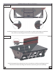
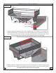
GC15t-1 Gravity Wagon Assembly STEP - 1 Install both Dumpside Corner Panels. Use (3) 8.8 M10 x 25 MM serrated flange hex head bolts and (3) M10 serrated flange hex head nuts to attach the panels to the shell. STEP - 2 Install the Dumpside Front Bottom Panel. Use (12) 8.8 M10 x 25 MM serrated flange hex head bolts and (12) M10 serrated flange hex head nuts to attach the panel to the shell body.
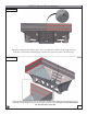
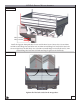
GC15t-1 Gravity Wagon Assembly STEP - 3 Install the Dumpside Rear Bottom Panel. Use (17) 8.8 M10 x 25 MM serrated flange hex head bolts and (17) 8.8 M10 serrated flange hex head nuts to attach the panel to the shell body. STEP - 4 Install the Rear Bottom Panel. Use (17) 8.8 M10 x 25 MM serrated flange hex head bolts and (17) 8.8 M10 serrated flange hex head nuts to attach the panel to the shell body. Do not install a bolt into the hole that is encircled.
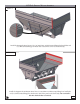
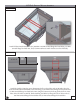
GC15t-1 Gravity Wagon Assembly STEP - 5 Install the Dumpside Rear Corner. Use (11) 8.8 M10 x 25 MM serrated flange hex head bolts and (11) M10 serrated flange hex head nuts to attach the corner to the shell body. STEP - 6 Install the Opposite Front Bottom Panel. Use (17) 8.8 M10 x 25 MM serrated flange hex head bolts and (17) M10 serrated flange hex head nuts to attach the panel to the shell body. Do not install a bolt into the hole that is encircled.
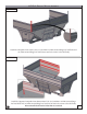
GC15t-1 Gravity Wagon Assembly STEP - 7 Install the Dumpside Front Corner. Use (11) 8.8 M10 x 25 MM serrated flange hex head bolts and (11) M10 serrated flange hex head nuts to attach the corner to the shell body. STEP - 8 Install the Opposite Dumpside Front Bottom Panel. Use (13) 8.8 M10 x 25 MM serrated flange hex head bolts and (13) M10 serrated flange hex head nuts to attach the corner to the shell body. Do not install a bolt into the holes that are encircled.
GC15t-1 Gravity Wagon Assembly STEP - 9 M12 x 25MM M12 x 25MM Install the Opposite Dumpside Front Corner and the Front Corner Gusset. Use (16) 8.8 M10 x 25 MM serrated flange hex head bolts and (16) M10 serrated flange hex head nuts to attach the corner and gusset to the shell body. Use (2) 8.8 M12 serrated flange hex head bolts and (2) M12 serrated flange hex head nuts to finish attaching the gusset to the shell body. STEP - 10 Install the Opposite Dumpside Rear Bottom Panel. Use (20) 8.
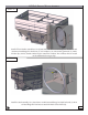
GC15t-1 Gravity Wagon Assembly STEP - 11 M12 x 25MM M12 x 25MM Install the Opposite Dumpside Rear Corner and the Rear Corner Gusset. Use (16) 8.8 M10 x 25 MM serrated flange hex head bolts and (16) M10 serrated flange hex head nuts to attach the corner and gusset to the shell body. Use (2) 8.8 M12 serrated flange hex head bolts and (2) M12 serrated flange hex head nuts to finish attaching the gusset to the shell body. STEP - 12 Tighten all of the bolts circled in the image above.
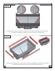
GC15t-1 Gravity Wagon Assembly STEP - 13 Install the Front and Rear Valleys. Use (16) 8.8 M10 x 25 MM serrated flange hex head bolts and (16) M10 serrated flange hex head nuts to attach the valleys to the shell body. STEP - 14 Install all four Sideboards. Use (32) 8.8 M10 x 25 MM serrated flange hex head bolts and (32) M10 serrated flange hex head nuts to attach the sideboards to the shell body.
GC15t-1 Gravity Wagon Assembly STEP - 15 Install all three Inside Braces. Use (12) 8.8 M10 x 25 MM serrated flange hex head bolts, (12) M10 serrated flange hex head nuts, and (12) M10 washers to attach the braces to the shell body. STEP - 16 58.10 CM 60.32 CM 89.69 CM Install the Ladder. Using the given dimensions, drill two thru holes with an M10 bit. Once the holes are drilled attach the ladder to the shell using (2) 8.8 M10 serrated flange hex head bolts and (2) M10 serrated flange hex head bolts.
GC15t-1 Gravity Wagon Assembly STEP - 17 Install all four Window assemblies. Use (8) 8.8 M10 x 25 MM serrated flange hex head bolts and (8) M10 serrated flange hex head nuts, (4) oval windows, (4) oval window grommets, (4) inside window clips, and (4) outside window clips to install the windows. The windows that are located on the sideboards do not get clips. STEP - 18 Install the Rack assembly. Use (4) 8.
GC15t-1 Gravity Wagon Assembly STEP - 19 Install the Rack Track Assembly. Slide the Track up through the opening in the door, then turn the Rack once the Track meets the gears on the Rack. Use (2) 8.8 M10 x 25 MM serrated flange hex head bolts and (2) M10 serrated flange hex head nuts to attach the Rack Track to the slide gate. Once the Rack Track is assembled tighten all hardware on the gravity wagon. STEP - 20 Install the Chute Guides. Use (4) 8.
GC15t-1 Gravity Wagon Assembly STEP - 21 Install the Chute. Use (2) zinc plated snap rings, and (2) 1/2” x 2-1/8” flat washers, to mount the Chute to the Chute Guides. OPTIONAL STEP - 22 Install the Center-dump Chute. Use (2) 3/8-16 x 1-1/2” hex bolts and (2) 3/8”-16 hex nuts to attach the Chute to the shell. Slide the bolt through the chute, then turn the nut on to the bolt. Once the bolt is on, turn the bolt into the tapped hole which is located on the tab welded to the shell.
GC15t-1 Gravity Wagon Assembly STEP - 23 Install the Chains. Use (2) 8.8 M10 x 25 MM serrated flange hex head bolts and (2) M10 serrated flange hex head nuts to install the Chains. STEP - 24 Install the Manual Holder. Use (2) 1/4”-20 x 1” carriage bolts and (2) 1/4” hex nuts to attach the Manual Holder to the front leg.
GC15t-1 Gravity Wagon Assembly STEP - 25 Install the Wire Wrap Bar. Use (2) 1/4”-20 x 3/4” self tapping screws to install the bar. Self tap your first screw at the labeled dimension. Do not tighten the screw all of the way. Now level the wirewrap bar to the ground. Install the last screw. Completely tighten both self tapping screws. STEP - 26 Begin to assemble the 16 Ton Running Gear. Start by sliding the Coupling Pole Weldment through the Rear Axle and the Retaining Ring.
GC15t-1 Gravity Wagon Assembly STEP - 27 Attach the Front Axle to the Coupling Pole Weldment. From the bottom, attach the Front Axle with (3) 1” x 6-1/2” hex bolts and (3) 1” centerlock hex nuts. STEP - 28 Attach the tongue to the front axle. Use a 1-1/4” Kingpin, 1-1/4” flat washer, and (2) 1-1/4” centerlock hex nuts to attach the tongue to the front axle. Then snap the (2) tongue springs in place.
GC15t-1 Gravity Wagon Assembly STEP - 29 Mount all four tires to the hubs. Use (8) 5/8” flange lugnuts to install each tire. The lugnuts need to torqued at 400 ft. lbs. STEP - 30 Install the brake system. Start with attaching the rubber hose to the Master Cylinder. Next run the brake line through the Front axle to the Tee in the brake line. Now run two brake lines from the Tee. Run one to each brake assembly. Tighten all of the brake lines once installed.
STEP - 30 CONTINUED GC15t-1 Gravity Wagon Assembly Secure the brake line with zip ties. STEP - 31 3225 Lbs 1463 Kgs Transfer the Shell body onto the 16 ton running gear. Use an appropriately rated chain to safely carry the shell body. Attach the chain inside of both red circles.
GC15t-1 Gravity Wagon Assembly STEP - 32 Attach the shell body to the 16 ton running gear. Starting in the rear, use (4) 1/2” x 6” hex bolts, (4) 1/2” centerlock hex nuts, (8) 1/2” flat washers, a 7/8” x 8” hex bolt, (2) 7/8” flat washers, and a 7/8” centerlock hex nut to join the shell body and running gear. Tighten all of the hardware installed in this step. Only tighten the 7/8” centerlock hex nut an 1/8” past the end of the bolt. STEP - 33 These washers are used as shims.
GC15t-1 Gravity Wagon Assembly STEP - 34 Install the wiring harness. Run the harness through the steel runner starting from the front. After installation, plug the harness into make sure the lights are working properly.
The parts manual will be available online after 3/15/2013. Find it at www.jm-inc.