O P E R A T O R ’ S M A N U A L and Set-Up Instructions for G R AV I T Y BOXES 750SD Gravity Box J. & M. Mfg. Co., Inc. P.O. Box 547 Ft. Recovery, OH 45846 Ph: (419) 375-2376 Fax: (419) 375-2708 JMMAN0101 (Rev. 08/01/05) www.jm-inc.
TO THE DEALER: Read manual instructions and safety rules. Make sure all items on the Dealer’s Pre-Delivery and Delivery Check Lists in the Operator’s Manual are completed before releasing equipment to the owner. The dealer must complete the Warranty Registration Card attached to the inside of this manual and return to J. & M. Mfg. Co. Inc. at the address indicated on the card. Warranty claims will be denied if the Warranty Registration Card has not been completed and returned. EXPRESS WARRANTY: J. & M.
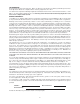
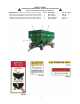
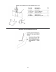
750SD GRAVITY BOX SPECIFICATIONS DIMENSIONS A) 192” B) 100” C) 129” D) 92” E) 157” F) 114” G) 296” H) 16” SPECIFICATIONS Capacity* Door Width Chute Height** Understructure Taillights Front Ladder Hopper Construction Weight 750 bushels 48” 19” 3/8” x 3” x 6” Runners Standard Standard 12 GA 7,050 lbs. (750SD Box with 24 Ton Running Gear and 18-22.5 Tires) * Bushel capacity measured with #2 corn at 15% moisture (56 lbs. test weight) ** Measured with 18-22.
GENERAL INFORMATION BOLT TORQUE CHART Always tighten hardware to these values unless a different torque or tightening procedure is listed for a specific application. Fasteners must always be replaced with the same grade as specified in the manual parts list. Always use the proper tool for tightening hardware: SAE for SAE hardware and Metric for metric hardware. Make sure fastener threads are clean and you start thread engagement properly.
TABLE OF CONTENTS INTRODUCTION 2 EXPRESS WARRANTY 2 SPECIFICATIONS 3 GENERAL INFORMATION 3 BOLT TORQUE CHART 4 SAFETY RULES 6 SAFETY SIGNS 7 OPERATION 8 ROUTINE MAINTENANCE 8 PARTS LIST/DIAGRAMS 9-10 LIGHT KIT 11-12 SERVICE RECORDS 13 5
SAFETY RULES ATTENTION! BECOME ALERT! YOUR SAFETY IS INVOLVED! Safety is a primary concern in the design and manufacture of our products. Unfortunately, our efforts to provide safe equipment can be erased by an operator’s single careless act. In addition, hazard control and accident prevention are dependent upon the awareness, concern, judgement, and proper training of personnel involved in the operation, transport, maintenance and storage of equipment.
50-16 OWNER’S MANUAL SAFETY SIGNS ATTENTION! BECOME ALERT! YOUR SAFETY IS INVOLVED! Replace Immediately If Damaged or Missing! IMPORTANT: Install new safety signs if the old signs are destroyed, lost, painted over or cannot be read. When parts are replaced that have safety signs, make sure you install a new sign with each new part. New signs are available from the manufacturer or your authorized dealer. 7 Ref.
750-16 OWNER’S MANUAL OPERATING INSTRUCTION / MAINTENANCE BE CERTAIN THAT ALL POWER IS SHUT OFF BEFORE SERVICING THE GRAVITY BOX.
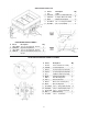
GRAVITY BOX PARTS LIST # Part # Description Qty 1 LL-8 Ladder 1 2 31617-CS 3/16" x 17" Chain w/S-hook 2 3 CWA-750 Complete Wheel Assembly 1 4 IWK-1 Window Kit Complete 2 5 381-HBN-F 3/8" x 1" Flange Bolt w/Nut 6 6 381-HBN 3/8" x 1" Bolt w/Nut 2 ROCKING BOLSTER ASSEMBLY # 1 2 3 4 Part # 78812-BNW URB-6750 12512-HBN 782B-LN Description 7/8" x 8 1/2" Bolt w/nut, washers Upper Rocking Bolster 1/2" x 5 1/2" Bolt w/nut, washers 7/8" x 2 1/4" Bolt w/lock nut, lock washer Qty 1 1 8 2
DOOR, CHUTE AND INSPECTION WINDOW PARTS LIST # Part # Description 1 D-750 Metering Door 1 2 GC-48 Grain Chute 1 3 IW-71212 Inspection Window 2 4 62095-7 Window Molding 2 5 WB-4 Window Brace 4 6 WB-4B Window Brace (rear) 4 MOUNTING THE CENTER DIVERTER CHUTE 10 Qty
GRAVITY BOX LIGHT INSTALLATION GUIDE GRAVITY BOX LIGHT KIT PARTS LIST # 1 2 3 4 5 6 7 8 9 10 11 12 13 14 15 16 17 18 19 20 21 22 23 Part # 7-WCE 7-WNB WH-1N LH-1 ----------LE-1B LT-R1 LT-A1 PG-1L RD-A1 RD-R1 RD-O1 141-CB 14-FN 181-HB 18-HN 1434-SDST WLC-1 SMV-2 WHB-1 RCW-1 OFL-1 Description 7-Wire Connector End 7-Wire Nose Box Main Wiring Harness Light Harness ------------------Light Enhancer Red Light Amber Light Plastic Grommet Amber Reflective Decal Red Reflective Decal Orange Reflective Decal 1/4" x
GRAVITY BOX LIGHT KIT SET UP INSTRUCTIONS: Slide the Main Wiring Harness 7-Prong Connector End through the Front Angle Bracket towards the hitch. The black and white wire and 7-Wire Nose Box on the Main Wiring Harness should run to the rear of the gravity box through either the steel runner or conduit. Place black Plastic Grommet around the circular cut-out of the Front Angle Bracket.
SERVICE / MAINTENANCE RECORD DATE DESCRIPTION NOTES 13