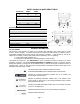
OPERATOR’S MANUAL Set-Up Instructions and Parts Catalog for Model 440SD or 540SD Gravity Box 440 or 540 Bushel Capacity Short Turn Design For 16 Ton Running Gears J. & M. Manufacturing Co., Inc. P.O. Box 547 Fort Recovery, OH 45846 Phone: (419) 375 2376 Fax: (419) 375-2708 E-mail: sales@jm-inc.com Website: www.jm-inc.com REV-10-04-08 Pg.
TO THE DEALER: Read manual instructions and safety rules. Make sure all items on the Dealer’s Pre-Delivery and Delivery Check Lists in the Operator’s Manual are completed before releasing equipment to the owner. The dealer must complete the Warranty Registration Card attached to the front inside cover of this manual and return to J. & M. Mfg. Co., Inc. at the address indicated on the card. Warranty claims will be denied if the Warranty Registration Card has not been completed and returned.
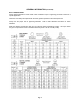
MODEL 540SD and 440SD GRAVITY BOX Dimensions 540SD 440SD A 180” 180” B 94” 81” C 120” 107” D 87” 87” E 124” 124” F 100” 100” G 248” 248” H 15” 15” F C H D Specifications Capacity 540 or 440 bushels Door Width 48” Chute Height Adjustable (14” to 19”) Understructure 9 GA 3” x 6” Tubing Taillights Standard Front Ladder Standard A B Center Diverter Chute Optional Hydraulic Drum Brakes Optional Hopper Construction 12 GA Weight (with running gear) 5,250 lbs (540SD)
GENERAL INFORMATION (continued) BOLT TORQUE CHART Always tighten hardware to these values unless a different torque or tightening procedure is listed for a specific application. Fasteners must always be replaced with the same grade as specified in the manual parts list. Always use the proper tool for tightening hardware. hardware. SAE for SAE hardware and Metric for metric Make sure fastener threads are clean and you start the thread engagement properly.
TABLE OF CONTENTS INTRODUCTION 2 EXPRESS WARRANTY 2 SPECIFICATIONS 3 GENERAL INFORMATION 3 BOLT TORQUE CHART 4 SAFETY SIGNS 5 SAFETY RULES 6 OPERATING INSTRUCTIONS / MAINTENANCE 7 PARTS LIST / DIAGRAM 8-10 LIGHT KIT 11-12 SERVICE RECORDS 13 SAFETY SIGNS IMPORTANT: Install new safety signs if the old signs are destroyed, lost, painted over or cannot be read. When parts are replaced that have safety signs, make sure you install a new sign with each new part.
SAFETY RULES ATTENTION! BECOME ALERT! YOUR SAFETY IS INVOLVED! Safety is a primary concern in the design and manufacture of our products. Unfortunately, our efforts to provide safe equipment can be erased by an operator’s single careless act. In addition, hazard control and accident prevention are dependent upon the awareness, concern, judgment, and proper training of personnel involved in the operation, transport, maintenance and storage of equipment.
OPERATION INSTRUCTIONS / /MAINTENANCE WARNING - BE CERTAIN THAT ALL POWER IS SHUT OFF BEFORE SERVICING EQUIPMENT.
MODEL 540SD and 440SD REPAIR PARTS LIST Sideboard Installation Note: Sideboards, Endboards, Corners and Sideboard Braces are used only on 540SD Gravity Box.
MODEL 540SD and 440SD REPAIR PARTS LIST Door, Chute and Inspection Window # Part # Description 1 D-540M Metering Door Grain Chute 2 GC-680 15 381-HBN-F 3/8” x 1” Flange Bolt with Nut 18 38-FW 3/8” Flat Washer 19 38-LW 3/8” Large Washer 20 CTE-LP Lynch Pin 21 ACB-1 Adjustable Chute Bracket Gear Reduction Wheel Assembly # Part # Description 1 TCA-28 Track and Chain Assembly 2 10T50B 10 Tooth Sprocket 3 38TSS 38 Tooth Sprocket and Shaft 4 15TSS 15 Tooth Sprocket and Shaft
MODEL 540SD and 440SD REPAIR PARTS LIST Center Diverter Chute Assembly Instructions 1. Locate the plates on both underneath sides of the door. There is a 3/8” tapped hole located on each plate. Attach the Center Diverter Chute using one 3/8” hex bolt, washer and lock nut as shown. 3/8” Nut 3/8” Bolt 3/8” Tapped Hole Side Dump Chute Box Plate Center Diverter Chute Diverter Chute Insert the 3/8” bolt through the pre-punched hole in the chute.
GRAVITY BOX LIGHT KIT REPAIR PARTS LIST PARTS LIST # Part # Description 1 7-WCE 7-Wire Connector End 2 7-WNB 7-Wire Nose Box 3 WH-1 Main Wiring Harness 4 LH-1 Light Harness 7 LE-1B Light Enhancer 8 LT-R1 Red Light 9 LT-A1 Amber Light 10 PG-1L Plastic Grommet 11 RD-A1 Amber Reflective Decal 12 RD-R1 Red Reflective Decal 13 RD-O1 Orange Reflective Decal 14 141-CB 1/4” x 1” Carriage Bolt 15 14-FN 1/4” Flange Nut 16 181-HB 1/8” x 1” Hex Bolt 17 18-HB 1/8” Hex Nut
GRAVITY BOX LIGHT KIT SET-UP INSTRUCTIONS: Slide the Main Wiring Harness 7-Prong Connector End through the lower front end of the gravity wagon toward the hitch. The black and white wire and 7-Wire Nose Box should run to the back end of the gravity box through the steel runner or conduit. Place the black Plastic Grommet around the circular cut-out of the Front Angle Bracket. Secure the black and white wire along the steel runner to the door opening of the gravity box for the door light.
SERVICE / MAINTENANCE RECORD Date Description Notes Pg.