MEGA RADIO REMOTE CONTROL SYSTEM -PRELIMINARYINSTALLATION AND OPERATION MANUAL J&M 3A2391BJ.
MEGA REMOTE INDEX DESCRIPTION ................................................................................... 2 TRANSMITTER AND RECEIVER SYNCHRONIZATION .......................... 2 INDICATOR LEDs .............................................................................. 4 LCD DISPLAY .................................................................................... 4 OUTPUTS .......................................................................................... 4 INSTALLATION ................
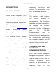
MEGA REMOTE DESCRIPTION equipment the art on 2 AA alkaline batteries. microprocessor based Radio Frequency (RF) The system’s radio receiver control system. It will provide has the operator the ability to All follow all OSHA www.osha.gov when harnesses interface such and tools RS-232 used for any software updates via the optional Palm interface tool.
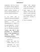
MEGA REMOTE transmitter with the correct display ID code/RF channel sequence when you should apply for which it is set. This feature power to the receiver allows multiple systems 3. Apply to will power indicate to the work in close proximity to one receiver. The Green LED another without interference. stays on when teaching is in progress and it will In the event that blink when teaching is a complete transmitter becomes damaged 4.
MEGA REMOTE INDICATOR LEDs overload protection. The outputs can also detect a noThe receiver identify module problems with can load or broken wire condition. the system in the form of an error These code. Check the red indicator evident on the receiver to diagnose indicator system problems. Then, refer module or the HISTOGRAM to the ERROR CODE CHART in page on the optional Palm this manual for explanation of Pilot™.
MEGA REMOTE with the down. connectors Please to insure good contact. facing take extra caution not to internal components All damage absorbing use must be properly insulated to protect while against shorts. installing. For high vibration applications, connections shock mounts. It Seal all connections with a is advised to mount the unit as non-conductive high as grease to prevent corrosion.
MEGA REMOTE used) for period greater than manual. 15 minutes. The user must press the POWER button at OPERATION this module for to restore transmitter operation. Power must be applied to the receiver point the The transmitter will NOT go system to work. to sleep as long as the receiver has power applied Pressing the POWER button to it. will turn on the transmitter.
MEGA REMOTE first unit to change is the Holding the scroll button on weight, start the weight to dispense page blinking. Using the UP/DOWN for 4 seconds, will get the unit buttons the weight can be into auto mode again . which will changed, to move to the next Enable/Disable Display unit press the SCROLL once which will give the control to change the default Holding the pushbutton for Hold door.
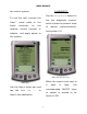
MEGA REMOTE DIAGNOSTIC the control system. Tap the Diagnostic button to To use this tool, connect the Palm™ serial cable serial connector to on see the diagnostic screens, the which shows the present state the of receiver control harness or remote communications, and system I/O. adaptor, and apply power to the system. RF Communications Page When the round circle next to Main Page a Use the Palm’s stylus pen and tap the icon J&M 1.
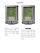
MEGA REMOTE Digital Inputs Pages ON/OFF Outputs Page Tap the Next Page button to HISTOGRAM switch of Tap the Histogram icon to see inputs. Tap the button labeled a set of screens that show Outputs between to pages view output which error codes are active screens. and how many times the specific error code has been active.
MEGA REMOTE FILE TRANSFER Tap the File Transfer button to send new program files from the Palm to the receiver. New programs are uploaded to the Palm via the Palm™ desktop as a *.pdb file using HotSync™. Histogram Page This feature can be used to troubleshoot machine wiring and other problems. Tapping the Reset button resets the error code counts. The password to reset error codes is 1262.
MEGA REMOTE CALIBRATION To change the configuration of the outputs, tap the Calibration icon. Output selection menu To adjust output’s a proportional configuration, use the following procedure: 1. Select Calibration page change these from the to first 2. Select the parameter of to the calibration screens is In output drop-down menu The password to gain access 1262. the the screens, output to change configuration for proportional from the second drop- outputs is available.
MEGA REMOTE by tapping on the line and using the scratch pad to enter a new value 4. Tap the Save button to send the setting to memory The lines to the right of the parameter indicate the present value of the output (if active). Calibration parameters menu Tap the Factory Setting button to return all outputs to standard values. Tap Save to send these settings to memory. Tap Done and Exit to quit configuration and return to the main menu. The following can be adjusted as needed: 1.
MEGA REMOTE 2.
MEGA REMOTE ROUTINE MAINTENANCE Clean carrying out any maintenance work. transmitter regularly Do not have hydraulic power with a damp cloth and mild available to the valves when detergent. performing electrical tests. Inspect electrical wiring for Never operate or test any wear points or other damage. function if any person is in an Repair as required. area where they could be hurt Inspect all looseness connections or Tighten by being hit or squeezed by for the hydraulic equipment.
MEGA REMOTE TECH representative for instructions or further servicing.
MEGA REMOTE TROUBLESHOOTING CHART PROBLEM 1. No functions work SOLUTION 1. on Check that transmitter power is 2. Check that receiver power is on 3. Check system wiring for power into the system 4. Check LED system status status display for 5. Check for proper grounding of system's electrical circuit 6. 2. Certain functions do not work Check system's hydraulic system 1. Check the wiring connection from the system to the valve coil for the output function that does not work 2.
MEGA REMOTE ERROR CODES Error code explanations: 1 Transmitter is off Transmitter went to sleep mode Interference in RF communication link 2 Transmitter and receiver are not synchronized 3 The RS-232 communication cable between the scale unit and the receiver is damaged, disconnected, or the scale unit is off 4 System voltage is below 10.
MEGA REMOTE PARTS LIST PART NUMBER DESCRIPTION 3A2392A RADIO TRANSMITTER 3A2393B RADIO RECEIVER There are no user-serviceable parts inside the transmitter or the receiver. Return the units for service. Note: For operation with negative ground systems only. WARNING: The MEGA REMOTE must be operated in compliance with all applicable safety regulations, rules, and practices. Failure to follow required safety practices may result in death or serious injury.
MEGA REMOTE TRANSMITTER PICTORIAL USES TWO (2) ALKALINE AA BATTERIES 1.44 3.15 POWER CONV START CONV STOP S C R O L L T A R E DN 6.17 UP F R O N T U P TIP SPOUT CONV SWING R E A R D O W N BOOM U P FRONT DOOR D O W N 1.
MEGA REMOTE RECEIVER PICTORIAL USER ASSIST DIAGNOSTIC THE FOLLOWING CHART ASSISTS THE USER IN TROUBLESHOOTING THE ELECTRICAL SYSTEM. ERROR CODE NUMBER IS THE NUMBER OF RED LED PULSES BETWEEN EVERY PAUSE. THERE ARE NO SERVICEABLE PARTS BEYOND THIS POINT. PLEASE CONTACT YOUR SERVICE PERSONNEL FOR FURTHER ASSISTANCE.
MEGA REMOTE SPECIFICATIONS FCC ID: P4U-VRTS Industry Canada Certification Number: 4534A-VRTS EQUIPMENT CLASS: PART 15 SPREAD SPECTRUM TRANSMITTER TRANSMITTER Power .................................................. 2 x AA alkaline batteries Operating temperature - Radio ........................... -20˚C to +85˚C Storage temperature ....................................... -40˚C to +100˚C RF Frequency ........................................................ 902-928 MHz RF Transmit power (EIRP) ...........
MEGA REMOTE INSTRUCTION TO THE USER This equipment has been tested and found to comply with the limits for a class B digital device, pursuant to part 15 of the FCC Rules. These limits are designed to provide reasonable protection against harmful interference in a residential installation. This equipment generates radio frequency energy and if not installed and used in accordance with the instructions, may cause harmful interference to radio communications.