
Data Sheet


CLA 80 E 1200 HF
tentative
(di/dt)
cr
A/µ
s
150
repetitive, I =
T
VJ
= 150°C
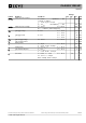
critical rate of rise of current
V
GT
gate trigger voltage
V= 6 V T = °C25
(dv/dt) T = 150 °C
critical rate of rise of voltage
A/µ
s
500
V/µ
s
f = 50 Hz; t = 200 µs
IA;
V = ⅔ V
R = ∞; method 1 (linear voltage rise)
VJ
D
VJ
Symbol Definition
Ratings
typ. max.min.Conditions
Uni
t
40 A
T
P
G
= 0.3 di /dt A/µs
G
=0.3
D
DRM
cr
V = ⅔ V
D DRM
GK
1000
1.5
V
T= °C-40
VJ
I
GT
gate trigger current
V= 6 V T = °C25
D
VJ
38 m
A
T= °C-40
VJ
1.6
V
80 m
A
V
GD
gate non-trigger voltage
T= °C
VJ
0.2
V
I
GD
gate non-trigger current
5m
A
V = ⅔ V
D DRM
150
latching current
T= °C
VJ
150 m
A
I
L
25tµs
p
=10
IA;
G
= 0.3 di /dt A/µs
G
=0.3
holding current
T= °C
VJ
100 m
A
I
H
25V= 6 V
D
R = ∞
GK
gate controlled delay time
T= °C
VJ
2µ
s
t
gd
25
IA;
G
= 0.3 di /dt A/µs
G
=0.3
V = ½ V
R DRM
turn-off time
T= °C
VJ
150 µ
s
t
q
25
di/dt = A/µs;20 dv/dt = V/µs20
V =
R
100 V; I A
T
=48
V = ⅔ V
D DRM
t
µs
p
= 200
non-repetitive, I = 50 A
T
;
IXYS reserves the right to change limits, conditions and dimensions. 20090602
Data according to IEC 60747and per diode unless otherwise specified
© 2009 IXYS all rights reserved