
Manual
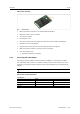
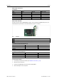
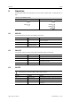
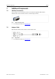
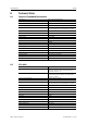
Table Of Contents

Operation
14 (22)
6 Operation
The implemented LEDs vary dependent on the variant of the USB-to-CAN
FD
. The PCIe Mini has no
LEDs.
LED Arrays of the Different Variants
Compact
Automotive
6.1 USB LED
The USB LED reflects the status of the USB communication.
LED state
Description
Comments
Off
No communication
Device not initialized, check power supply. Device not
connected to USB port.
Green
Communication possible Device is ready for use.
Red flashing State changes between
power saving and active
Changing power state.
6.2 CAN LED
The CAN LEDs reflect the status of the CAN communication (CAN 1 and CAN 2).
LED state
Description Comments
Off
No communication
No communication, device not connected to CAN
Green flashing
Communication present
LED is triggered with each message.
Red flashing Controller in error state Controller is in state error warning or state error passive,
communication is possible.
Red Bus off Controller is in state bus off, no communication possible.
6.3 LIN LED
LIN functionality is exclusively available on USB-to-CAN
FD
automotive.
LED state
Description
Comments
Off
No communication
No communication on LIN bus or device not connected to
LIN bus.
Green flashing
Communication present
LED is triggered with each message.
Red flashing Communication with errors On transmission or reception of a LIN message an error
was detected.
USB
CAN
USB
CAN1
CAN2
LIN
USB-to-CAN
FD
User Manual
4.01.0350.20000 1.5 en-US