
Manual
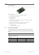
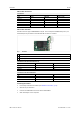
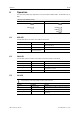
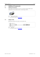
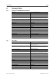
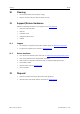
Table Of Contents

Installation 12 (22)
USB-to-CAN
FD
Automotive
Pin Allocation
RJ45, Pin No. Adapter cable
Signal
CAN 1
CAN 2/LIN
D-Sub 9, Pin No.
CAN high
1 1 7
CAN low
2 2 2
CAN GND 3, 7 3, 7 3, 6
LIN
-
6 5
VBAT
LIN
-
8 9
USB-to-CAN
FD
PCIe Mini
The CAN connector type is SM03B-SURS-TF by JST. The counterpart is 03SUR-32S by JST. A pre-
assembled open-style cable for each CAN and LIN connector is included.
Fig. 6 Connectors
1 CAN 1
2
CAN 2 (only supported in variant with 2 x CAN FD and LIN)
3
LIN (only supported in variant with 2 x CAN FD and LIN)
Pin Allocation PCIe Mini CAN FD Interface 1/2
Signal Pin No. Color
CAN high
1
Red
CAN low
2
Yellow
CAN GND 3
Black
Pin Allocation PCIe Mini LIN Interface 3
Signal Pin No. Color
VBAT
LIN
1
Red
LIN 2
Yellow
LIN GND 3
Black
Connecting the Fieldbus
► If necessary install bus termination (see CAN Bus Termination, p. 15).
► Observe the pin allocation.
► Connect the CAN fieldbus connector to the CAN fieldbus.
► Start canAnalyser on the computer.
USB-to-CAN
FD
User Manual
4.01.0350.20000 1.5 en-US