
Manual
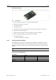
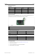
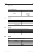
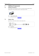
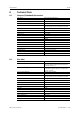
Table Of Contents

Installation 11 (22)
USB-to-CAN
FD
PCIe Mini
Fig. 5 PCIe connector
► Make sure that the computer in use supports USB via PCIe Mini.
► Make sure that the driver is installed.
► Turn off the computer.
► Pull the power cord.
► Open the computer case according to the instructions of the computer manufacturer.
► Determine the corresponding slot.
► Plug the PCIe connector (1) in the corresponding slot, without using force.
► Make sure that the interface is securely held in the computer.
► Close the computer case.
→ Hardware installation is complete.
5.2.2 Connecting the CAN Fieldbus
The assignment of the fieldbus connectors (D-Sub 9 and RJ45) is in accordance to CiA 303-1.
The shield of the CAN connector is connected to CAN ground via a 1 MΩ resistor and a 10 nF
capacitor. The shields of the CAN connectors of the variant automotive are connected directly
together.
For best noise immunity connect shields of the CAN cables directly to the device ground.
USB-to-CAN
FD
Compact/Embedded
Pin Allocation
Pin No.
Signal
RJ45
D-Sub 9
CAN high
1 7
CAN low
2 2
CAN GND 3, 7 3, 6
USB-to-CAN
FD
User Manual
4.01.0350.20000 1.5 en-US