
Manual
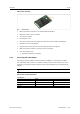
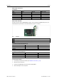
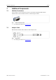
Table Of Contents

Installation 10 (22)
USB-to-CAN
FD
Embedded
Risk of ESD damages caused by improper handling!
Use ESD protective measures to avoid equipment damage.
Damage of the equipment because of reverse polarity or wrong type of power supply!
Make sure that the power supply is correctly connected and of recommend type.
Connector:
• USB cable with 5 pin female connector
• Assignment corresponds to PC standard for internal USB devices.
Fig. 4 Standard wire assignments 1x5 header connector female
1
Red: +5 V/voltage +/VCC
2
White: D-/data-/USB-
3
Green: D+/data+/USB+
4
Black: GND/voltage-/ground
5
Black: S-GND/over current/shielding
► Make sure that the driver is installed.
► Turn off the computer.
► Pull the power cord.
► Open the computer case according to the instructions of the computer manufacturer.
► Mount the slot bracket with embedded board in suitable slot.
► Plug the small plug of the USB cable in the USB connector of the embedded board.
► Plug the USB connector in the suitable connector on the computer main board.
► Close the computer case.
→ Hardware installation is complete.
1
2
3
4
5
USB-to-CAN
FD
User Manual
4.01.0350.20000 1.5 en-US