
User's Manual


Installing the 100W and 100WP ERT Module
TDC-0909-004 100W and 100WP Datalogging ERT Module Installation Guide 23
Proprietary and Confidential
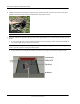
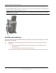
4. The installed ERT module position must be vertical and upright when the lid is replaced on the pit.
Caution When placing the pit lid on to the pit box after the shelf mount adapter installation, use care to
avoid pinching or damaging the ERT module to meter cable. Any ERT module position other than upright
may negatively affect radio performance and battery life.
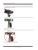
Through Lid Mount
This section provides instructions to mount the 100W and 100WP ERT module in a pit lid with a drilled,
round 1-3/4-inch, 1-7/8-inch, or 2-inch hole.
Caution Some pit lids have a molded, recessed cavity that allows Itron 40W-1, 50W-1, and
50W-2 ERT modules to sit flush with the top surface of the lid. However, the dome of the
ERT module retainer for the 100W or 100WP ERT module has a smaller diameter and does
not fill the pit lid cavity. This can cause the cavity to become a trip hazard. Itron does not
recommend using this type of pit lid with 100W and 100WP ERT modules.
Through Lid Mount Required Tools and Hardware
This mounting method requires the Pit Lid Mounting Kit. Refer to the 100W Installation Methods Overview
(PUB-1300-004) for guidance on which kit to install for different pit lid material and traffic conditions.
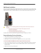
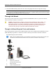
Pit Lid Mounting Kit (CFG-1300-004)
Note The Pit Lid Mounting Kit is not intended for applications involving vehicular traffic. Use
the Remote Antenna Kit in incidental traffic areas (such as residential environments).
D
A
Retainer clip
B
Pit lid with a pre-drilled hole
(simulated pit lid material shown)
C
Retainer clip collar
D
100W and 100WP ERT module