
User's Manual


Initializing, Connecting, and Programming the ERT Module
TDC-0909-004 100W and 100WP Datalogging ERT Module Installation Guide 10
Proprietary and Confidential
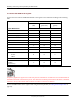
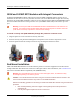
Connecting the 100WP to a Remote Meter Register
Connect the wires from the 100WP ERT module to the register screw terminals according to the following
table.
Register Manufacturer
100WP wire color
Red
(signal)
Black
(common)
White
(tamper)
Register screw color designator
Elster Digital
BLK
GRN
R
Itron (Actaris) Cyble Sensor (2-
wire)
Either wire
Remaining wire must be connected to both
ERT module wires
Badger RTR
R
BLK
Green/bare
Elster V100
BLK
R
Blue
Sensus PMM
R
BLK
Bare
Caution Wrap the wire one complete revolution around the register screw.
Completely tighten the register screw and verify the wire insulation is not under the screw terminal heads or
intermittent electrical connection may occur. You must use a moisture-proof sealant if the meter is installed
outdoors or in any environment where moisture can collect on the screw terminals.
Connect the ERT module to the register cable using the Itron Splice Kit (see Using the Itron Splice Kit on
page 41).
Using an Extension Cable
Order the 25-foot inline connector extension cable assembly (CFG-0151-401) to extend the 100W with the
inline connector.